METHOD STATEMENT FOR PIPE JACKING WORK
To install the CW underground pipeline of Vung Ang 2 Thermal Power Plant at crossing area with Vung Ang 1 belt conveyor by pipe jacking pressing method.
METHOD STATEMENT FOR PIPE JACKING WORK
INTRODUCTION
1.1 Introduction
The Vung Ang II thermal power plant is part of the Vung Ang thermal power center and is the second complex of the coal-fired electricity generating plant located in the Vung Ang industrial zone, Ky Loi commune, Ky Anh district, Ha Tinh province in Vietnam. Vung Ang II will be constructed adjacent to Vung Ang I which is already in operation. It consists of two turbines with a total capacity of 1,200 MW. Both will be fueled by imported anthracite, hard coal.
1.2 Abbreviation and definition
The Owner Vung Ang II Thermal Power LLC
The Contractor DHI-SCT Joint Venture
HSE Health, Safety and Environment
MS Method Statement
RA Risk Assessment
PPE Personal Protective Equipment
QA/QC Quality Assurance/Quality Control
1.3 Scope of work
To install the CW underground pipeline of Vung Ang 2 Thermal Power Plant at crossing area with Vung Ang 1 belt conveyor by pipe jacking pressing method.
1.3.1 Constructing of 04 CW pipelines with Diameter 2700mm
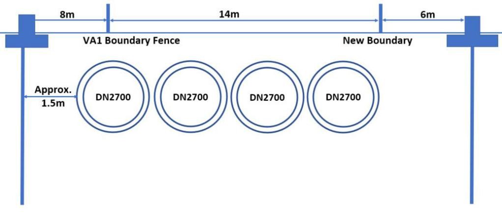
Number of CW pipelines can be changed with 2 pipelines (DN 3700) at the detail engineering stage
2 OVERVIEW
CW pipe DN2700 to install underground by Pipe jacking method.
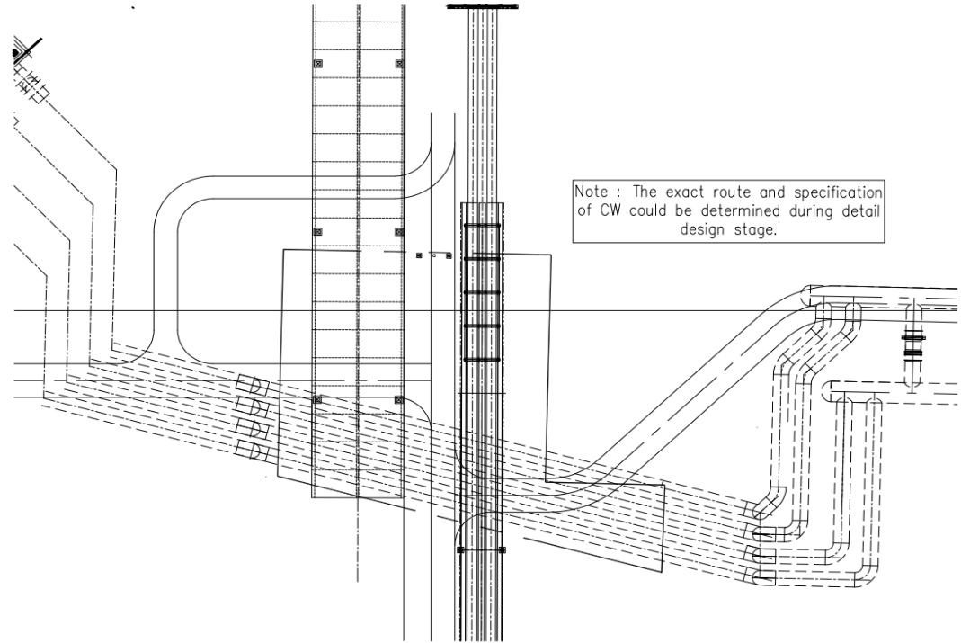
Plan View of Construction Location
Table 1.1 Contents of work
|
No |
Items |
Method statement |
Quantities |
Note |
|
A |
Shaft construction |
|
|
|
|
1 |
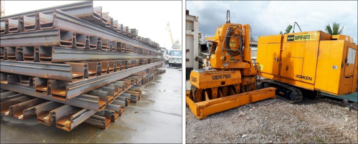
Driving and extract steel sheet pipe Larsen IV |
Use Silent Piler(100-150T) |
|
|
|
2 |
Soil improvement for bottom of shaft |
Jet Grouting D1800 |
2shaft |
|
|
3 |
Soil improvement for entrance of launching and arriving shaft |
Jet Grouting D1200 |
|
|
|
4 |
Strut installation |
Lifting and installing |
|
|
|
5 |
Soil Excavation |
Use excavator |
|
|
|
B |
Pipe jacking construction |
|
|
|
|
1 |
Supply DN2700 pipe |
|
|
|
|
2 |
Installation CW pipe DN2700 |
Pipe Jacking |
40m |
|
3 METHOD STATEMENT
3.1 Shaft construction
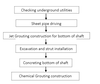
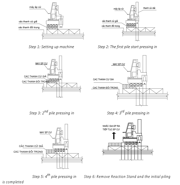
3.1.1 Construction sequence
3.1.2 Sheet pile construction
a. Preparation work
Approved all documents
Mobilization equipment and materials.
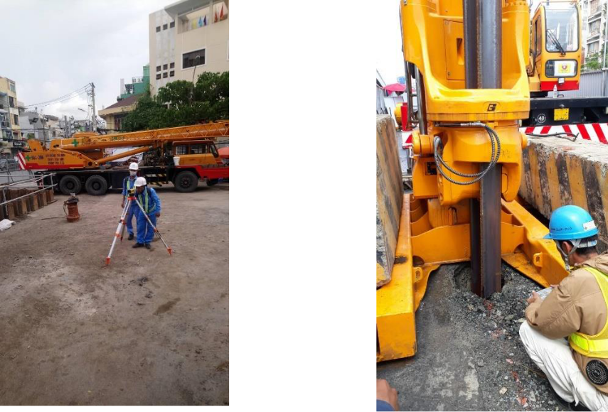
b. Survey work
Use total station machine to setting up.
Marking point by paint on the site.
Checking underground utilities.
c. Sheet pile driving
Checking weather before construction
Welding sheet pile with length of design.
Use crane to lifting sheet pile for driving.
Sheet pile driving with checking alignment by water ruler.
d. Cleaning after construction
Remove all materials and rubbish,
Keep clean of site.
e. Construction sequence
3.1.3 Jet Grouting construction
- General
Soil improvement is carried out at the bottom of shaft. The purpose of this work is protection and waterproofing for the shaft bottom during construction work.
Jet grouting method is able to meet the above these requirements
The statement consists of site preparation, materials supply and installation.
Typical design of Jet grouting at drivel shaft
- Method statement of Jet grouting work
Jet Grouting column will be carried out adopted the operating parameters
(such as Improved DIA, discharge flow, grouting pressure, Pulling up rate…) by experience.
JSG method is used High-pressure injection of cement slurry and air from double tube with rotation
Schematic diagram of Jet grouting
Material mixing:
The slurry shall be mixed continuously during the Jet grouting progress on site by the mixer. The slurry consumption will be calculated based on the fluid flow rate set up on the high pressure pump machine.
Bảng 3.1 Mixing proportion per 1.0m3
|
No |
Material |
Unit |
Quantity |
|
1 |
PCB40 |
Kg |
550 |
|
2 |
Water |
L |
822 |
- Operation parameters for Jet grouting
Bảng 3.2 Operating parameters for Jet grouting
|
Parameters |
Unit |
Diameter 1800mm |
Diameter 1200mm |
|
Pressure |
MPa |
20±2 |
20±2 |
|
Discharge rate of slurry |
L/min |
60± 2 |
60± 2 |
|
Rotation speed |
Rpm |
10-12 |
10-12 |
|
Pulling up rate of double tube |
Min/m |
35.0 |
21.0 |
- Sequence of Jet grouting work
+ Preparation work
- Utility services detection needs to be conducted thoroughly to check for any existing services. If there are utility services affecting the work, the effected services need to be duly exposed and well protected at the location of grouting to avoid damage.
- Access for equipment and man power will be made.
- Transportation of material shall be done using truck and unloading by manual labour or crane as necessary.
- Materials will be kept at designated locations with adequate protection.
- Workers will be trained for safety and acknowledge of the correct sequencing of work execution.
Communication on Site will be conducted via mobile phones and walkie-talkies.
+ Setting-up Equipment and Machinery
- Assemble the drilling machine on site.
- Attach the drilling machine with necessary mixing equipment (such as rod, monitor and bit) for Jet Grouting.
- Set up the cement mixing ratio as design parameters.
+ Drilling work
- Check the verticality of the drilling machine using the water level ruler that is attached to the drilling machine and the plumb-lines method from two perpendicular directions
- Check the nozzle that is used to inject the cement grout by visual inspection prior to the drilling works. A simple water test shall be conducted if necessary. The water test utilizes the injection of water into the rod tubes. If the water successfully emits from the nozzle, the nozzle is in good working condition.
- Check the pressure of the pump by visual inspection of the dial pressure gauge.
- Execute drilling of a small diameter bore-hole to the designated depth using low pressure water flushing from the bottom for the Jet grouting works.
- Measure and record the designated depth manually from the balance rod above the ground level and compared with the actual of the rod.
+ Jet grouting work
- After completing the drilling work, the operating mode will be switched from drilling mode to Jetting mode.
- Jetting pressure will be increased to 20 ± 2 Mpa and then Jetting mode is set.
- Control the grouting pressure by the dial pressure gauge.
- Record tip level by measure the length of drilling rod manually.
- Inject cement grout with ultra-high-pressure pump through the nozzle screen when the drill rod is slowly withdrawn from the bore-hole.
- The injection rate of grouting and withdraw rate will be decided base on operation parameter
- The removal or uplifting by rotation of the drill rod is carried out at a rate of 10-12 rpm
- Injection volume will record at a flow meter.
- If it came to unexpected high pressure, safety valve of the pump is activated.
+ Cleaning and Slime/ Slurry Disposal
- After completion of the grouting works, the equipment including rods and mixing plant shall be cleaned for the next position. All slime/ slurry is not allowed to spread over or outside of the work areas. To protect the spread of the slime, the pit shall be arranged near the working areas. The size of pit shall be determined to ensure that effluent cannot enter the public drainage system.
- Sludge disposal be collected in pits and shall be disposed of site daily by dump trucks to the approved dumping area.
QUALITY CONTROL/ QUALITY ASSURANCE
+ Quality control before construction
Before construction, the Contractor shall take samples of materials and carry out necessary test for all materials proposed to be used.
Jet grouting equipment shall be functional properly such as rotating and moving after grouting rod according to the pre-determined supplying ratio of grout from the mixing machine with the pre-determined pressure and volume.
Pressure gauge and others shall be used to measure construction parameters, which are necessary to be adjusted before construction.
+ Quality control during construction phase
Quality control during construction is controlled as following:
Bảng 3.3 Quality control of Jet grouting
|
Item |
Description |
Method |
Frequency |
Remarks |
|
Cement grout control |
Check the Grout density |
Using Mud-balance |
Random checking but not less than twice a day per rig. |
W/C ratio = 1.5:1 Grout density = 1,37± 0,05 |
|
Construction parameter control |
Jet grouting parameters: |
|||
|
• Flow rate of the fluid |
Checked by visual inspection of the pressure gauge. |
Carry out at all times during construction. |
60±2 litter
|
|
|
• Pressure of the fluid |
20±2 Mpa |
|||
|
• Pulling up rate of Triple tube |
Setup a prior to the construction. |
Diameter 1800mm: 35min /m Diameter 1200mm: 21min /m |
||
|
• Rotation speed of the Jet grouting string |
Visual inspection of the pressure gauge during Jet grouting phase. |
10-12 rpm |
||
|
Check the geometry of piles: |
||||
|
• Pile coordinate |
Check from benchmark by surveyor |
Setting machine. |
Maximum tolerance <50mm, unless otherwise specified) |
|
|
• The verticality of rod |
Check on the drilling rod |
Carry out at all times during construction. |
Tolerance : 1/100 |
|
|
• Length of pile or pile head level |
Measured by linear meters and check by length of drilling rod. |
|
||
- Daily construction report: weather, report all activities occur during a working day and report all unusual activity (loss of power, machinery breaks down…). During the construction of each Jet grouting column, it has to be recorded in details truthfully.
Learn more Underground drilling service >>
CÔNG TY CP TƯ VẤN ĐẦU TƯ & THIẾT KẾ XÂY DỰNG MINH PHƯƠNG
Địa chỉ: Số 28B Mai Thị Lựu, Phường Đa Kao, Q.1, TPHCM
Hotline: 0903649782 - (028) 3514 6426
Email: nguyenthanhmp156@gmail.com
Xem thêm