Explanatory report on construction methods for horizontal directional drilling (HDD)
The purpose of this document is to propose a method for the Project Management Consultant and the Investor to review and approve for the Contractor to execute and control the drilling process for pulling a steel pipe with a diameter of D200 under the road.
TABLE OF CONTENTS
4. OCCUPATIONAL SAFETY MEASURES, ENVIRONMENTAL HYGIENE, AND SITE SECURITY.. 6
4.2. Equipment operation regulations. 6
4.3. Fire Prevention and Fire Fighting Regulations. 6
1.1 Purpose of the Document
The purpose of this document is to propose a method for the Project Management Consultant and the Investor to review and approve for the Contractor to execute and supervise the construction of drilling and pulling operations for a steel pipeline with a diameter of D200.
1.2 Legal Documents
- Construction Law No. 50/2014/QH13 dated June 18, 2014, of the 13th National Assembly, 7th session;
- Environmental Protection Law No. 70/2022/QH14 effective from January 1, 2022, of the 14th National Assembly;
- Decree No. 15/2021/ND-CP dated March 3, 2021, of the Government detailing a number of contents on construction investment project management;
- Decree No. 06/2021/ND-CP dated January 26, 2021, of the Government detailing a number of contents on quality management, construction, and maintenance of construction works;
- Decree No. 11/2010/ND-CP dated February 24, 2010, of the Government on the management and protection of road traffic infrastructure;
- Decree No. 117/2021/ND-CP dated December 22, 2021, of the Government amending and supplementing a number of articles of Decree No. 11/2010/ND-CP dated February 24, 2010, on the management and protection of road traffic infrastructure.
2. CONSTRUCTION SCHEDULE
- The construction schedule is established from the date the Investor receives the construction approval permit.
- Expected construction schedule: 30 days
3.1 Technical Solutions
Based on the actual site survey and the project's requirements, the contractor proposes the following construction method and steel pipe:
- Construction method using horizontal drilling technology with HDD (Horizontal Directional Drilling) machine.
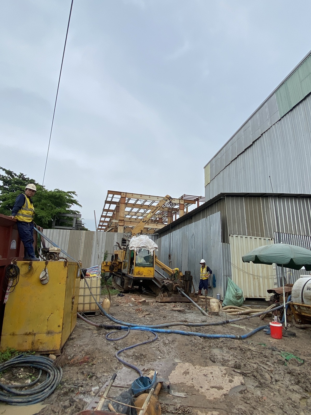
- Construction plan: Excavating construction pits on both sides of the river and using a horizontal directional drilling machine first, then expanding the drilling hole to the required size to pull the steel pipe.
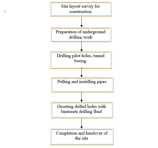
Diagram of underground drilling technology:
Figure 1. Construction technology diagram
- Main construction steps:
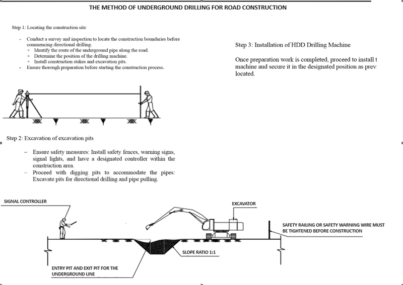
Step 1: Locating the pipeline route, positioning the drilling machine, placing construction piles, and digging pits.
Survey and assess the actual soil conditions, existing obstacles (such as underground cables, pipelines, drainage pipes), determine the placement of the drilling machine and pipes, prepare the site for pulling, consolidate construction methods, equipment, materials, anticipate potential obstacles, and propose solutions to accelerate the schedule.
Locate the pipeline alignment, position construction piles, and mark excavation pits.
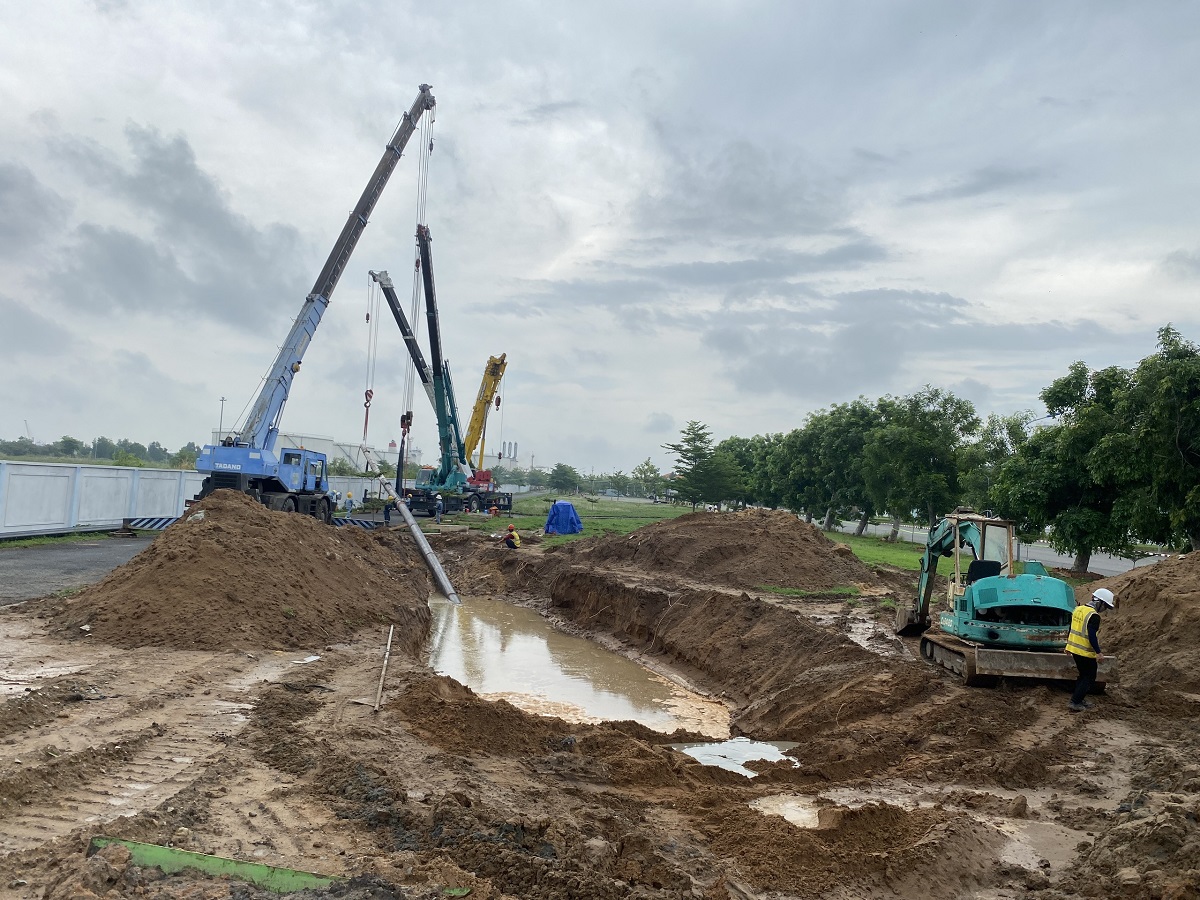
Step 2: Excavate the excavation pits
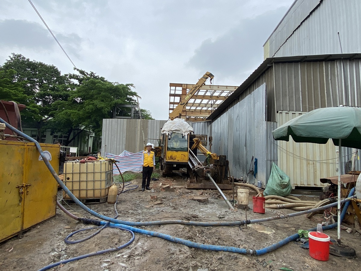
- Constructing protective fencing around the construction site: Erecting protective fences and installing safety signs for both daytime and nighttime. The construction area for the drilling machine and other equipment is approximately 40m x 20m. The receiving area for the pipes is 50m x 25m.
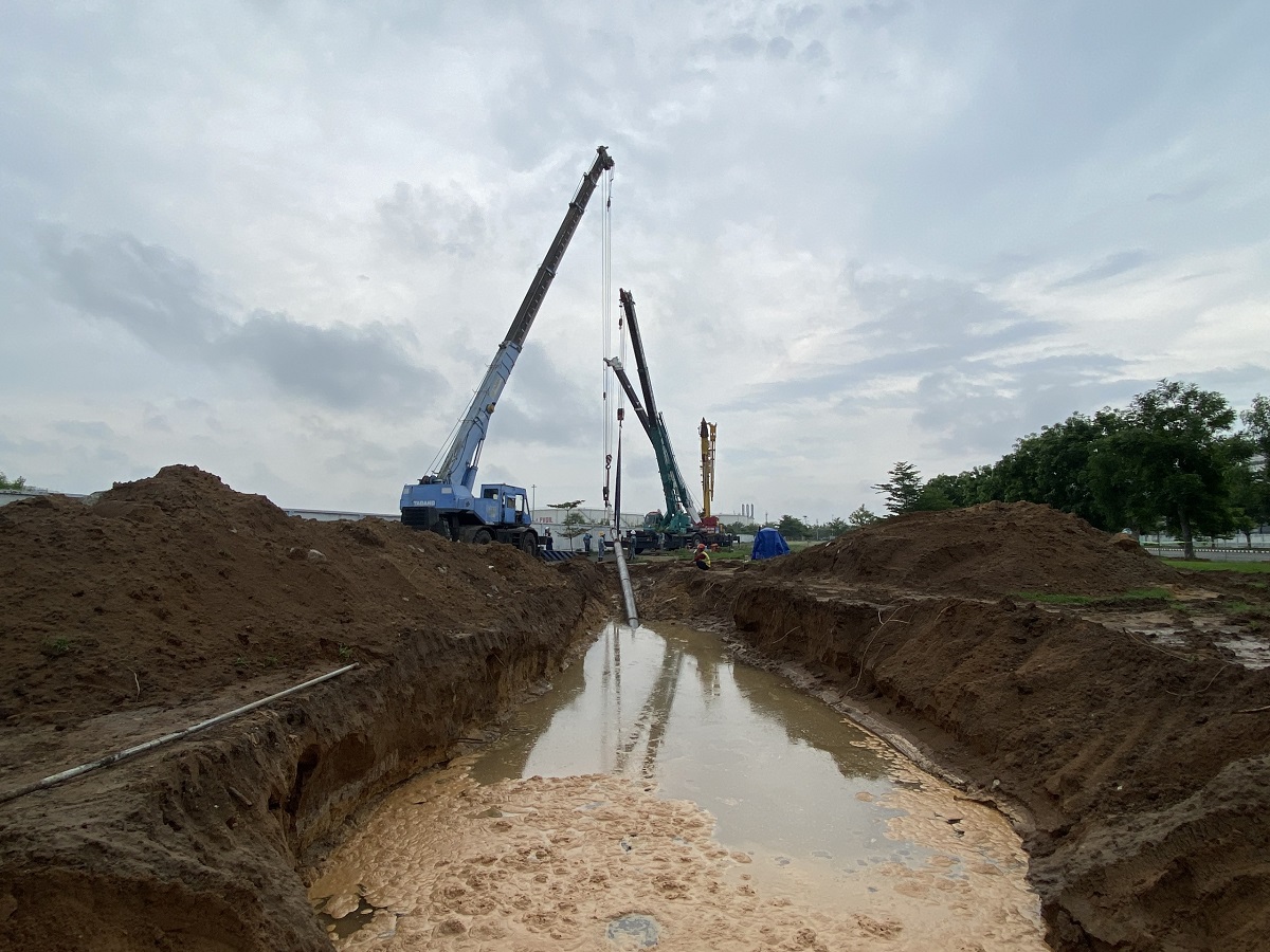
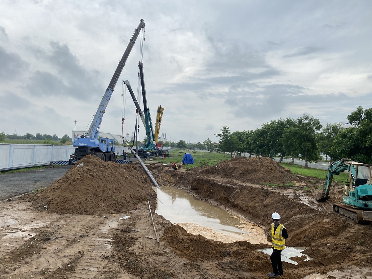
- Excavating the pipe receiving pit: The receiving pit is excavated to a depth of 4-4.5 meters below the road surface (0.5 meters deeper than the pipe depth). This pit serves to clear the drilled hole, receive the pipes, and facilitate the use of a winch to guide the pipes. The contractor will use a dewatering pump to remove groundwater or corrosion testing water from the steel pipe receiving area.
- Excavating the drilling and pulling pit: To facilitate drilling and installing pipes at a depth of 4-4.5 meters below ground level. This pit provides the construction area for the drilling rig, drilling tower, access, and operation of pipe pulling.
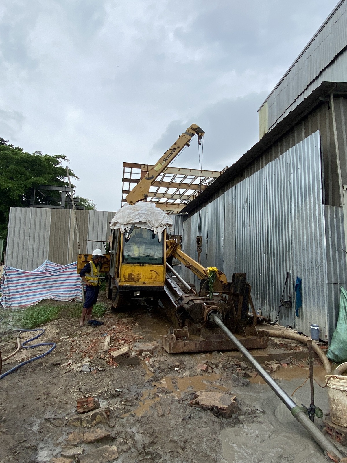
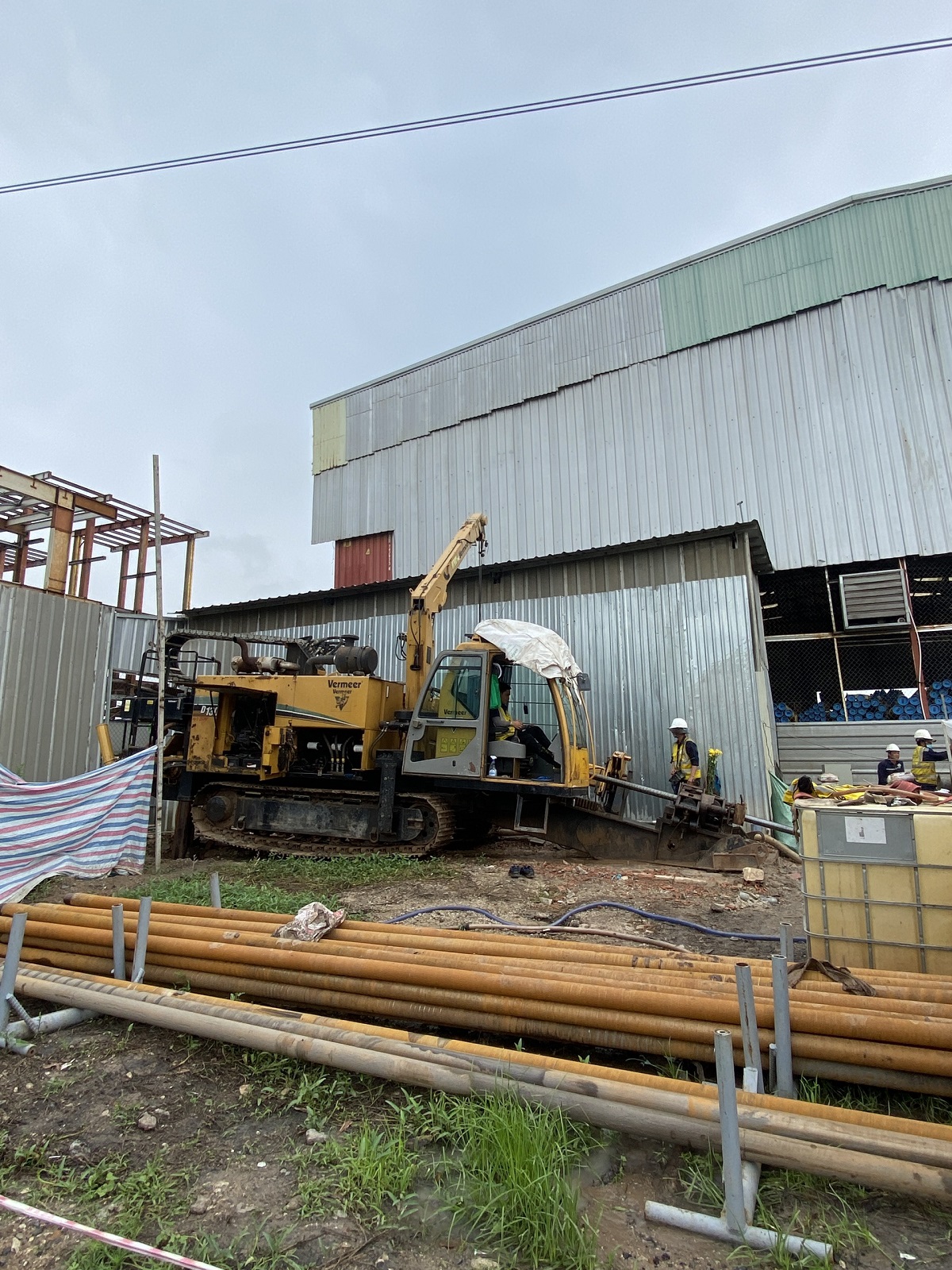
Step 3: Installing the HDD drilling machine
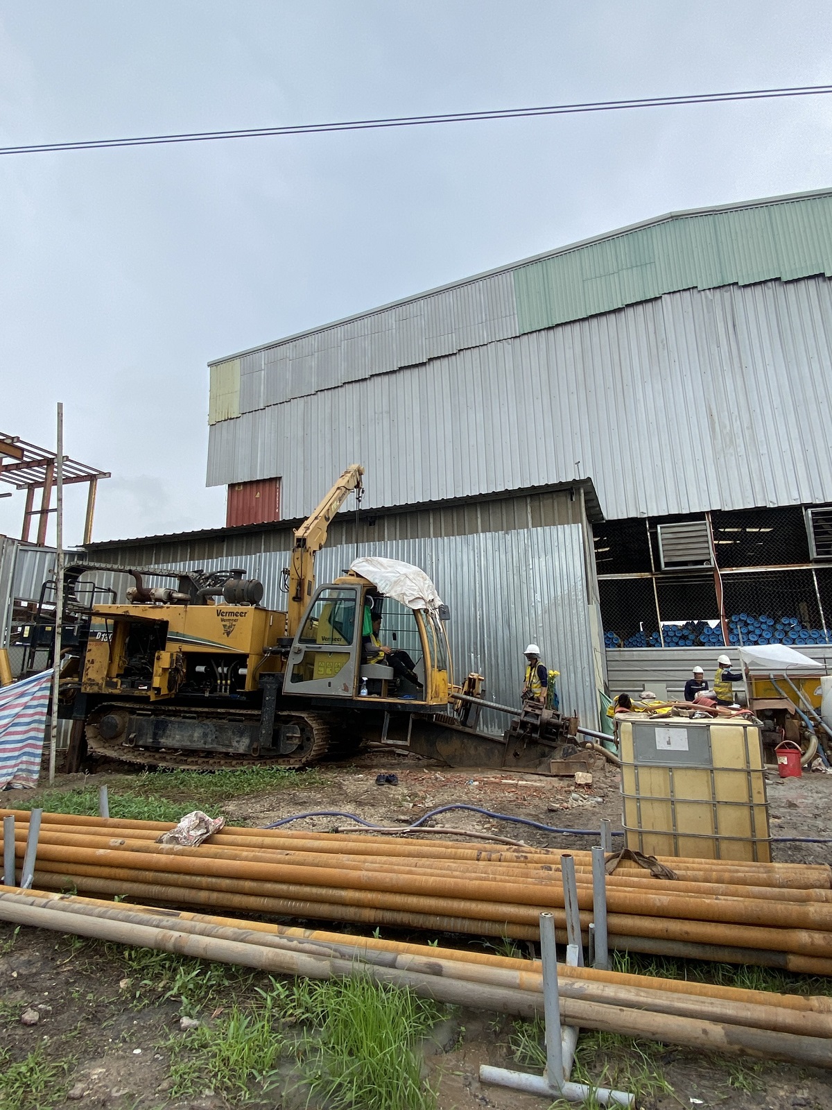
Proceed with positioning and securely installing the HDD drilling machine.
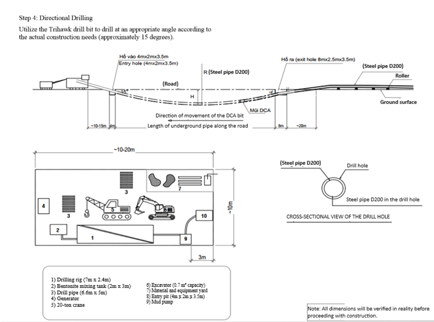
Step 4: Directional drilling
Figure 2: Directional drilling pilot hole
Using a TriHawk drill bit to drill at an appropriate angle.
Setting initial parameters (thrust force, drilling speed, drilling angle...) to meet design requirements.
When the drill bit reaches the designated change direction point as per the design, adjust the drill bit inclination to the appropriate angle and thrust force to gradually change the direction until achieving a horizontal path at the predetermined depth according to the design. Then continue the horizontal journey using the push-rotate technique until reaching the upward direction change point. Continue adjusting the drill bit inclination to the "12 o'clock" position and applying thrust force to advance towards the pre-defined target point. Throughout the drilling process, drilling fluid is pumped down to lubricate and reinforce the drill hole.
The guidance is adjusted to follow the exact direction of the design route. The directional drilling speed can vary depending on soil conditions and the required turning angle.
The entire signal for guiding the drill head's movement is determined by a transmitter located within the drill head. This transmitter must operate continuously throughout the drilling process and ensure it can transmit signals up to a minimum distance of 25 meters upward.
These details are transmitted wirelessly to the remote display unit installed on the drilling machine, allowing the operator to guide the drill head according to the design specifications using the Digitrak F5 Falcon positioning device.
The directional drilling path must be closely controlled to follow a predetermined route as specified by the design and adhere strictly to allowable slope gradients. During directional drilling, a drilling log is maintained for each drill rod (6m), recording drilling angle and drill bit depth data to serve as the basis for monitoring and acceptance criteria later on. The allowable device error is ±5% concerning depth measurements.
At the control stakes on the construction site, the elevation will be verified using the Digitrak device transmitting vertically from the drill head, recorded on the remote display unit controlled by technical personnel. Alternatively, for depths less than 4 meters, excavation pits may be dug to verify elevation.
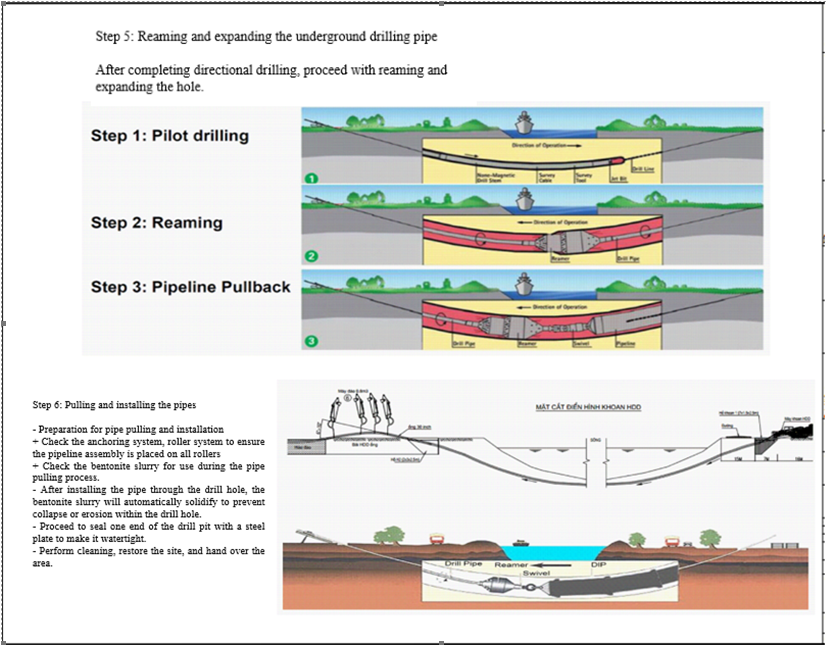
Step 5: Reaming the drilled hole to expand the bore diameter
After completing the directional drilling, the drill head and TriHawk drill bit will be replaced with a back reamer to sequentially expand the borehole diameter as follows:
Reaming with a 300mm diameter back reamer:
Applying the push-pull technique to retract the back reamer back to the drilling machine at a speed of 3-5 feet per minute, depending on the geological conditions of the construction area. The speed may vary to suit the geological layers the drill path passes through, accompanied by pumping a compatible drilling fluid to create a tunnel for pipe pulling.
- In the case of clayey soil conditions at the construction site, the reaming speed is approximately 5 feet per hour, which translates to about 1.5 meters per hour.
- If encountering stiff or plastic clay geological layers at the construction site, the reaming speed would be approximately 3 feet per hour.
The back reamer has a diameter of D = 1.2 to 1.5 times the diameter of the pipe (minimum 120% of the pipe diameter needed for tunneling). Operating the back reamer must adhere to calculated procedures based on geological data of the project to ensure the structural integrity of the tunnel walls for maintaining high-quality drilling fluid circulation inside.
Step 6: Pulling and installing the pipe
Preparing for pipe pulling:
- Check the anchor system of the rig and ensure the roller system is in place to support the pipe string on all rollers.
- Check the bentonite drilling fluid for the pipe pulling process.
After installing the steel pipe through the drilled hole, the bentonite drilling fluid will automatically solidify to prevent erosion within the borehole, ensuring the structural integrity of both the borehole wall and the existing ground. Once the pipes are installed according to the design, one end of the drilling pit is sealed with a steel plate to close off the receiving pit, preventing mud, dirt, or debris from entering the pipe.
The receiving pit and the construction pit are cleaned thoroughly before handing over for further work on connecting the pipe system and completing the site.
The reverse flow of mud and water mixture at the drill pit and pipe pulling pit will be pumped into specialized vehicles and transported to a designated disposal site following regulations.
3.2. Conclusion
The construction measures have been calculated and checked for feasibility. However, the following points need consideration:
- Detailed and accurate geological survey and groundwater levels are necessary for the pipeline construction.
- Surveying the elevation profile along the pipeline route during the current conditions is essential for construction planning.
Please forward to the Project Management Board and Investor for review and decision.
4. Occupational Safety Measures, Environmental Hygiene, and Site Security
4.1. General Regulations
Safety procedures must be applied to all Engineers, Supervisors, and Workers working at the construction site.
Ensure that all Personal Protective Equipment (PPE) such as helmets, safety boots, goggles, gloves, masks, etc., are provided on-site before commencing work.
- Ensure that PPE is worn correctly while working.
- Machines and equipment must be inspected by authorized personnel before use. Electrical equipment must have separate circuit breakers to prevent overload incidents.
- Barriers and warning signs will be installed on-site
4.2. Equipment operation regulations
- Before operation, a detailed plan must be prepared.
- Operators must understand safety protocols.
- Supervision must be rigorous.
- Ensure all tools are prepared.
- Inspect equipment prior to operation.
- Remove obstacles within the operating area.
- Ensure the ground is flat and stable.
4.3. Fire Prevention and Fire Fighting Regulations
Fire prevention and firefighting are prioritized throughout the construction process. Fire prevention involves organizing and implementing technical measures to prevent fires from occurring, limit their spread, effectively extinguish fires, and ensure safe evacuation of people and property.
- Strictly adhere to the traffic safety procedures throughout the construction period in the construction site area.
- Disseminate the fire safety regulations for the steel pipeline to all staff and workers involved in the construction.
- Always ensure there are at least 2 fire extinguishers available at the construction site
4.4. Environmental Hygiene Regulations
During the construction process, potential environmental impacts may include pollution such as:
- Soil and rock dust pollution impacting workers directly at the construction site.
- Pollution from waste generated by transport vehicles and construction machinery.
- Noise pollution from transport vehicles and construction motorcycles.
Measures to minimize environmental impact include pollution control, dust prevention, and noise mitigation. Specifically, at the construction site, the contractor will implement the following tasks:
- Daily site cleaning will be conducted after each workday, ensuring compliance with construction laws and regulations.
- All waste materials will be cleared at the end of each shift and disposed of at designated dumping sites within the construction premises, in accordance with regulations.
4.5. Order and Security
- When the contractor participates in construction, the list of officials and workers involved will be registered with the security department of the investor.
- Based on this list, the contractor's security department will be issued access cards by the investor's security department.
Below is the information on the construction method for drilling and pulling a steel pipe with a diameter of D200 under the road at the Ben Luc - Long An expressway toll station. Minh Phương company is the leading provider of robotic underground drilling services in Vietnam, having completed numerous underground drilling projects nationwide. Customers and partners who need consultation and a quote for underground drilling, please contact us immediately for the fastest support!
CÔNG TY CP TƯ VẤN ĐẦU TƯ & THIẾT KẾ XÂY DỰNG MINH PHƯƠNG
Địa chỉ: Số 28B Mai Thị Lựu, Phường Đa Kao, Q.1, TPHCM
Hotline: 0903649782 - (028) 3514 6426
Email: nguyenthanhmp156@gmail.com

Xem thêm