Horizontal Directional Drilling (HDD) Process for Gas Pipeline Project
This purpose of this document is to describe in general terms the HDD process and methodologies that will be utilized for “Approximately 94 km of 30-inch onshore pipeline from An Minh Landfall Station to O Mon Gas Distribution Center (GDC) at Can Tho Province” section this project.
2.1. HDD Work Site Preparation 9
3. ORGANIZATION CHART AND RESPONSIBILITIES 13
3.7. Community Relation (CR) Manager 16
3.10. Emergency Response Team 18
4. HDD DESIGN AND ENGINEERING 19
4.1. Design and Engineering Software 19
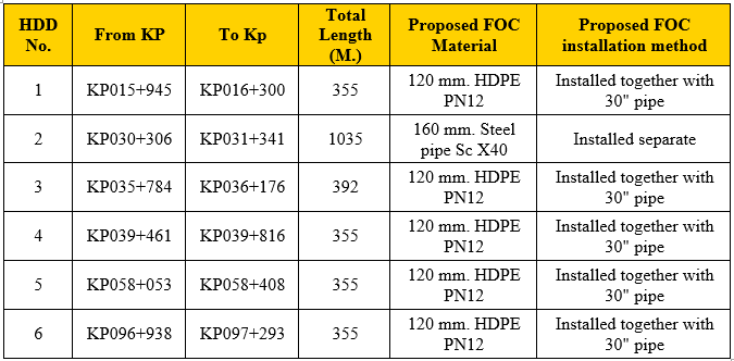
4.3. Fibre Optic Conduit (FOC) Design 21
4.4. Engineering Document reviewed 21
5.2. General Sequence of the Works 23
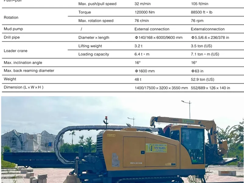
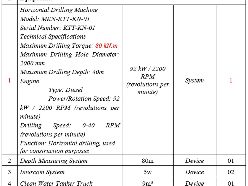
6. EQUIPMENT / DOWNHOLE TOOLS 25
7.2. Drilling Fluid Waste Disposal 32
7.4. Drilling Fluid Product 32
7.5. Drilling Fluid Parameters 32
7.6. Cuttings Treatment & Displacement Removal 33
8. HDD SEQUENCE OF OPERATION 34
8.3. Preparation and Installation of Product Pipe 37
8.4. Installation of Product Pipe 39
ANNEX A – DESIGNED PULLING HEAD 50
ANNEX B – PULLING HEAD CALCULATION 51
ANNEX C – OVERBEND ARRANGEMENT 52
1.INTRODUCTION
1.1 Project Overview
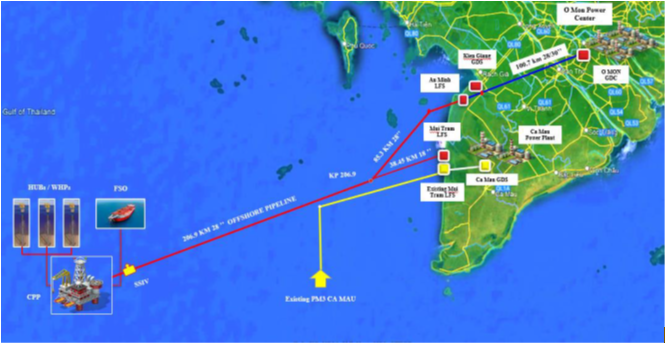
South West Pipeline Operating Company (SWPOC) hereafter referred to as COMPANY is responsible for development of Block B – O Mon Gas Pipeline to transport natural gas from Block B, 48/95 & 52/97 located in Southwest Sea of Vietnam to supply gas to the power plants at O Mon Power Centre, supplement gas for Ca Mau Gas – Power – Fertilizer Complex and other customers at Southwest area. The overall project includes about 431.69 km of offshore and onshore gas pipelines passing through 03 provinces/cities including Ca Mau, Kien Giang and Can Tho.
1.2 Project Description
The Block B-O Mon Gas Pipeline Project includes the following facilities:
- The offshore pipeline has a total length of 330.69 km, of which:
- Approximately 292.24 km of 28-inch offshore pipeline from Subsea Isolation Valve (SSIV) downstream flange to An Minh Landfall Point (LFP) at Kien Giang province.
- Approximately 38.45 km of 18-inch spur offshore pipeline from KP 206.9 to approach Mui Tram Landfall Station (LFS) at Ca Mau province.
- The onshore pipeline has a total length of 102.8 km, of which:
- Approximately 7 km of 28-inch onshore pipeline from An Minh Landfall Point to An Minh Landfall Station (LFS) at Kien Giang province.
- Approximately 94 km of 30-inch onshore pipeline from An Minh Landfall Station to O Mon Gas Distribution Center (GDC) at Can Tho Province.
- Approximately 0.4 km of 18-inch onshore pipeline from Mui Tram LFP to Mui Tram LFS at Ca Mau province.
- Two (02) LFS’s at An Minh and Mui Tram, six (06) Line Block Valve Stations (LBV), one (01) O Mon GDC.South West Pipeline.
1.3 Purpose
This purpose of this document is to describe in general terms the HDD process and methodologies that will be utilized for “Approximately 94 km of 30-inch onshore pipeline from An Minh Landfall Station to O Mon Gas Distribution Center (GDC) at Can Tho Province” section this project. Due to the nature of the drilling process, the sequencing and method is subject to change depending on the prevailing conditions.
1.4 Reference Document
|
No. |
Document Number |
OWNER Doc. Number |
Document Title |
|
[1] |
|
|
HDD Profile Drawing – Pipeline Crossing River/Road |
|
[2] |
|
|
TOPOGRAPHIC MAP WITH SCALE 1/500 FOR HDD LOCATION |
|
[3] |
|
SWG-PTSCL18-EPC-00-TE-SPC-0001 |
SPECIFICATION FOR |
|
[4] |
TELECOMMUNICATION AND EQUIPMENT |
|
|
|
[5] |
|
SWG-PTSCL18-EPC-70-SV-REP-0003 |
REPORT FOR SOIL INVESTIGATION OF ONSHORE |
1.5 Definitions
|
Term |
Meaning |
|
Owner |
|
|
Main contractor |
|
|
Sub contractor |
|
1.6 Abbreviations
|
Term |
Meaning |
|
ATL |
Allowable Tensile Load |
|
FEED |
Front End Engineering Design |
|
HDD |
Horizontal Directional Drilling |
|
ID |
Internal Diameter |
|
IFR |
Issued For Review |
|
ISO |
International Organization for Standardization |
|
OD |
Outside Diameter |
|
PRCI |
Pipeline Research Council International |
|
SPS |
Safe Pull Tensile Stress |
1.7 Scope of Work
The HDD works will consist of the separate installation of 30” steel pipe with FOC conduit at 6 locations detail describe below.
|
HDD No. |
From |
To |
Location |
Total Length |
|
1 |
KP015+945 |
KP016+300 |
Highway 63 and Xang Xeo Ro Canal |
355 |
|
2 |
KP030+306 |
KP031+341 |
Cai Lon River |
1035 |
|
3 |
KP035+784 |
KP036+176 |
Cai Lon River |
392 |
|
4 |
KP039+461 |
KP039+816 |
High Way 61 |
355 |
|
5 |
KP058+053 |
KP058+408 |
Thot Not Canal and Seal Province road |
355 |
|
6 |
KP096+938 |
KP097+293 |
High Way 91 |
35 |
1.8 Pipe Detail
The product pipe to be installed at each HDD crossing is as following detail.
Main Product pipe
|
Pipe Material |
Steel |
||
|
Pipe Grade |
APL 5L GR. X65M |
||
|
D |
Product outside diameter |
0.762 m. |
30.00 in. |
|
D |
Product inside diameter |
0.723 m. |
28.50 in. |
|
r |
Product radius |
0.381 m. |
|
|
t |
Pipe wall thickness |
19.10 mm. |
|
|
ct |
Coating thickness |
3.30 mm. |
|
FOC Casing for HDD 2
|
Pipe Material |
Steel |
||
|
Pipe Grade |
SCh x40 |
||
|
D |
Product outside diameter |
m. |
6.00 in. |
|
D |
Product inside diameter |
m |
in. |
|
r |
Product radius |
m. |
|
|
t |
Pipe wall thickness |
mm. |
|
FOC Casing for HDD1,3,4,5&6
|
Pipe Material |
HDPE |
||
|
Pipe Grade |
PN12.5 |
||
|
D |
Product outside diameter |
m. |
4.00 in. |
|
D |
Product inside diameter |
m. |
in. |
|
r |
Product radius |
m. |
|
|
t |
Pipe wall thickness |
mm. |
|
|
ct |
Coating thickness |
mm. |
|
2. GENERAL
All works to establish and maintain the HDD construction sites shall be performed in compliance with the HDD site layouts shown in HDD Site Layout and the project safety and environmental documents.
2.1 HDD Work Site Preparation
The HDD work site will be stripped and prepared by Main contractor prior to Sub contractor arriving at site. Sub contractor will check at handover of site from Main contractor that access roads and site clearance is in accordance with agreed scope and suitable for Sub contractor requirements.
Prior to mobilization of HDD related equipment to the HDD site location the site will be prepared to enable delivery, set-up and operation of all equipment safely during the execution of the works. Access roads on the site will be constructed to allow access. The short term lease access road will be constructed by Main contractor before hand- over to Sub contractor.
The backfill material will be sourced from approved quarries and will be brought by dump trucks along the existing roads.
At each drilling entry and exit point location an elevated hardstanding will be constructed which the HDD rig and its support equipment will be positioned on.
The site preparation will address the following:
- HDD Site Survey and marking of reference points relevant for construction
- Installation of access road to HDD rig pad suitable for HDD equipment
- Levelling and compacting of the HDD rig pad, site fill and hardstand (Refer to drawing)
- Marking the entry point and verification
- Provision of site facilities, i.e. office, restrooms, parking area, etc.
- Installation of rig anchor for HDD drilling rig according to approved design
In the project there are 6 HDD Locations. At each HDD location, the HDD entry exit site and access
2.2 HSE
Prior to commencing work all personnel shall have attended the specified HSE induction in accordance with project requirements. No work shall be undertaken by personnel who have not attended the HSE Induction. At kick-off and for new crew a review of task plans and of risk assessments will be performed. Owner and Main contractor stop work policy will be implemented, i.e. everyone can stop work when feel unsafe; work to be continued by site PIC.
2.2.1 Communication
Communication between personnel on both the onshore and offshore spread will be by two- way radios. Channels in use shall be agreed before arrival at site. A base station will be installed in the site office. Hand held radios will be available for use on site with radio checks performed at the start of each day and spare batteries available if required. In the event of temporary communications breakdown, mobile phones will be used to establish contact until radio communications are re-established. No operations between onshore and offshore will continue unless reliable communications are in place.
Before rotating or pushing/pulling any part of the drill string, the Driller will ask confirmation from the crew on other site that it is safe to do so. During pullback operations the Driller in the will not commence any pulling operations unless given the all-clear by exit site supervisor. For different languages and nationalities on site, the main emergency commands such as all stop will be in English only.
2.2.2 Pre Start Meeting
Tool Box talks shall be undertaken at the start of each shift for onshore and offshore (and combined where applicable), before any new activities or at any other time required. They shall be managed by the shift supervisor and shall detail the expected scope of work for the shift or activity with roles and responsibilities defined. Personnel shall be reminded that they are to only follow the procedures defined for the activity.
2.2.3 Maintenance of Equipment
All SUBCONTRACTOR equipment will be maintained on site in accordance with OEM recommended guidelines. Spares will be mobilized as per Manufacturers’ recommendations. Maintenance and inspection records will be kept on site.
2.2.4 Reporting & Records
The driller will record all notable operational functions during all stages of the pilot hole drilling, reaming and installation. The driller’s records are independent to the survey data and information recorded by the downhole surveyor. The data recorded and included in the daily report by the on-shift driller / superintendent is considered the definitive log not only for actual drilling activities but also general operational activities with regard to stoppages and delays to the works.
Copies shall be provided by Subcontractor upon completion of the individual stages of the drilling operations. Drilling Log will be available for review by Company representative onsite.
Outlined are the various operational points that are recorded for each drill pipe installed and removed from the hole. The data recorded forms the basis for the ongoing works with regard to mud mixing, tooling choice and hole condition. The parameters detailed for drilling logs will show the following:
- Drill pipe number and length
- Start Time
- Finish Time
- Pump (mins)
- Downtime(mins)
- Drill time(mins)
- Req ( Az/Incl)
- Drill (Az/Incl)
- Thrust (Tons)
- Push and Pull Forces – bar
- Rotary/Torque - psi
- Pumping Volume – l/min
- Pump Pressure – (on/off)
- Comments - general on drilling conditions, stoppages etc.
- Mud weight.
The following documents will be provided separately, in addition to the daily progress report for example forms;
- Survey logs
- Mud Logs
- As Built- Package upon completion of individual crossings.
3. ORGANIZATION CHART AND RESPONSIBILITIES
Project organization chart and CV of key position are in Appendix 1. Each key position’s responsibilities are described as below.
3.1 HDD Manager
-
HDD Manager shall report to Construction manager. HDD Manager shall be responsible for:
- Lead team of HDD supervisor, each responsible for the operation of the HDD rigs.
- Preparation of HDD design document with the support of the Field engineer, Review sub contractor’s design, Work packages and associated field engineering. Co-ordination with OWNER for approval.
- Preparation of HDD crossings Plan, equipment and manpower deployment.
- Participate in recruitment / selection of Expert and specialized manpower for the operation of the HDD rigs.
- Estimation of additional working area requirement and co-ordination with CR for land leasing as per the construction schedule.
- Co-ordination with Sub contractors, construction team for the site access, entry and exit Area for the installation of equipment.
- Co-ordinate with Construction team for preparation of Pipe Strings and its testing. Plan and ensure that all support equipment is available in time and as per the requirement of the HDD operations.
- Supervise equipment Installation, operation and completion of all HDD operations till pull back and restoration of the site.
- Ensure all Maintenance during operation with due coordination with the Plant & Equipment Manager, preventive maintenance, tracking and upkeep of all records.
- Requisition for Procurement of consumables, tools and tackles and ensure that all required material is available at Stores. Review the preservation and security of the material. Responsible for providing in time the support equipment to sub-contractor with due coordination with the Plant & Equipment Manager
- To supervise and plan timely transportation of all HDD equipment from one location to another location with due coordination with the Plant & Equipment Manager. For required Traffic management coordinate with the SHE manager.
- Management of waste transportation, disposal to designated dumpsite and management of frac out incident, co-ordination with CR and SHE manager.
- Support CR and Permit team for obtaining necessary permits for the HDD works.
- Record all construction data, co-ordinate inspection by OWNER/Consultant, As-built data and markup drawings for HDD works.
3.2 HDD Supervisor
-
He shall report to HDD manager, be responsible for execution and implementation of all site activities related to HDD work, records HDD data and prepare construction reports. He shall also be responsible for the co-ordination to ensure that all consumables, spares and project material is available at site.
- The HDD supervisor is also responsible to co-ordinate with other construction crews such as site preparation, pipe transportation and stringing, welding and hydrotesting, joint coating, roller installation and pipeline pulling activities.
- HDD supervisor shall be present at work site all the time and will be the team leader of the HDD operation crew.
3.3 HDD Operator
-
HDD Operator will be based at work site and shall be directly operating the HDD rig to ensure that drilling operation is carried out in line with approved design. He will be coordinating with the surveyor.
3.4 Surveyor
Surveyor shall be responsible for the following:
- Surveyor shall conduct pre-construction survey to make the centerline of the Pipeline, entry and exit points, Rid anchor location etc, so that site preparation activities are carried out.
- Surveyor shall also be responsible to check the co-ordinate of the tunneling head and perform the calculation and provide feedback to Operator to make course correction and ensure that the hole centerline is limited to the Pipeline axis.
- HDD Supervisor and Surveyor shall closely co-ordinate with operator to ensure that all survey during operation has been shared with Operator promptly.
- Shall be responsible for calibration of HDD survey equipment
3.5 HDD Engineer
-
He shall report to HDD manager, be responsible for execution and implementation of all site activities related to HDD work, records HDD data and prepare construction reports. He shall also be responsible for the co-ordination to ensure that all consumables, spares and project material is available at site.
- The HDD supervisor is also responsible to co-ordinate with other construction crews such as site preparation, pipe transportation and stringing, welding and hydrotesting, joint coating, roller installation and pipeline pulling activities.
- HDD supervisor shall be present at work site all the time and will be the team leader of the HDD operation crew
3.6 QA/QC Inspector
-
QC Engineer reports to Quality manager, QC Engineer is responsible for:
- Implement, conduct and manage the QA/QC Programs as per the Project Quality Plan.
- Prepare Inspection Test Plan (ITP) for construction activities
- Prepare all QC Procedure as per ITP
- Review work procedures and method statements for compliance with good work practices and the customers contract requirement and specifications.
- Coordinate all inspections, monitor the required tests and record inspections and tests as per the Inspection and Test Plan (ITP) and Contract Specifications. Co-ordinate with OWNER for Witness/ Review as per Project Specifications and Work Procedures.
- Witness and Reviewing the inspection and testing methods and procedures for Radiographic, Dye Penetrant, Magnetic Particle, and Ultrasonic inspections
- Co-ordination with External Inspection agencies such as NDT (Auto UT, X-Ray, DP Testing, Magnetic testing, etc) at site.
- Liaise with the OWNER's representatives for the conduct of day-to-day quality related project activities.
- Ensure that Non-Conformance Report (NCR) are raised once the activities deviated from the Contract Specifications and Maintain a tracking system to monitor the status of NCR
- Maintain and Manage Tools and Test Equipment Calibration logs.
- Prepare Quality status reports, attend Weekly Meeting and alert the project team of any potential problems.
- Support Construction team for Work Test pack preparation
- Review all inspection reports for compliance.
- Coordinate with the customers QC inspectors for the resolution of site problem.
3.7 Community Relation (CR) Manager
-
Community Relation manager (CRM) reports directly to the Construction Manager.
- CRM shall head the Community relations and liaising department and responsible for Community Relation, Permits and temporary land acquisition.
- CRM shall be well versed with problems which affect the Community during the execution of the Project and shall reach out to the Community for informing them about the Project.
- CRM shall manage the Complaint Management Cell and hear to the grievances and problems of the community and find out a solution in consultation with the CM.
- CRMshall be a bridge between the Construction team and the community.
- CRM will be responsible for additional land acquisition and obtaining permits from the concerned Government authorities.
- CRM will also cover the Permit co-ordination and ensure that required permits are available in time for smooth construction.
- CRM will be based at main site office and support by team of Permit Officers.
3.8 SHE Manager
Though administratively under the Project Manager, the SHE Manager has direct access to the Project Director / Sponsor. He shall be stationed at main site office. SHE manager will lead a team of Safety officers, Environment Specialist, safety technicians as per the contract requirement and Thailand law and regulations.
SHE manager is responsible for:
- Implementation of the SHE program. As SHE administrator, the site SHE Manger shall function as advisor, consultant to the site Management, Supervisory personnel, sub-contractor’s SHE organizations, in establishing and maintaining compliance with local laws and regulations, OWNER SHE requirements.
- He shall compile, monitor and report Safety statistics and identify trends and areas requiring more attention, risk reduction or systems improvement.
- Shall co-ordinate for OWNER Safety inspection / walkabout sessions.
- Identify site specific requirements of statutory bodies.
- Formulate and implements plans to comply with statutory bodies.
- Organize meetings and presentations to disseminate statutory requirements.
- Organie the procurement of Safety material such as PPE, Safety sign boards, barricading tapes, barriers, etc and ensure adequate inventory.
- Ensure the deployed equipment meets the statutory requirements as well as ensure safety inspections records are maintained and made available on requirements basis at the project sites.
- Develop site specific traffic management plan, diversions and adequate implementation at site. Support CR for necessary permits in this regard.
- Approve, co-ordinates and executes the SHE training plan, Deploy adequate Safety and environment management personnel (as per regulations) throughout the construction site at all locations to ensure that safety regulations and measures are enforced.
- Organize and conduct Safety Audit and shall liaise with the OWNER,Act as the SHE auditing focal point & liaison with Auditor. Audits are included in the overall audit schedule.
- Review risk assessment and job safety & Environmental analysis prepared by the execution team.
- Conduct incident/ accident reporting, analysis and root cause analysis.
3.9 Safety Officer
Safety Leader Reports to HSE Manager and Safety officer reports to Safety Leader. Both the Safety Leader and Safety officer are located at construction site.
The responsibility of Safety officer is as follows:
- Organise Safety material such as PPE, Safety sign boards, barricading tapes, barriers, cones etc are available at site and implemented as per the plan.
- Ensure the deployed equipment meets the statutory requirements as well as ensure safety inspections records are maintained and made available on requirements basis at the project sites.
- Implement site specific traffic management plan, diversions and adequate implementation at site.
- Conduct Tool box meeting
- Ensure that operations have been conducted as per HSE procedures and all operating personnel follows the same.
- Co-ordinate with OWNER /Consultant HSE manager and ensure that instructions are followed
3.10 Emergency Response Team
Emergency Response team shall be responsible for the following:
- Emergency response team shall take care of following emergency needs:
- Incidents and accidents involving fatality or major injury to personnel Medical cases requiring resources not readily available at the work location.
- Adverse weather conditions
- Environmental pollution or damage
- Emergency response team shall be responsible for the Frac out management and co-ordinate with HDD rig operation team (especially driller) to issue direct instructions to slowdown and stop the HDD activities in case of Frac out.
- Handling of Frac out drilling fluid in such a manner that no further damage occurs to the environment and habitation.
- Containment of the Frac out fluid and immediate evacuation to the dump location.
- Corrective action and restoration once the Frac out is contained and stopped.
4. HDD DESIGN AND ENGINEERING
Prior to commence HDD work all drawings, procedures and calculation shall be submitted and approved by the Owner.
- HDD Construction crossing drawing
- HDD Site specific construction procedure
- HDD Site lay out drawing
- HDD Pull back and Stress calculation
- HDD Overbending design and calculations
4.1 Design and Engineering Software
The follow program and software will be used to design and calculated the HDD document for this project.
- AutoCAD
- Rig Anchor
- Excel
4.2 Design Parameter
All HDD crossing shall follow this parameter. The design of HDD crossing will follow these parameters and design to achieve each specific HDD location requirement.
Entry Angle: 7-12 Degrees
Exit Angle: 5-9 Degrees
Min Combined Bend Radius: 900 m.
Over Bend Radius: 500 m.

Figure 1 HDD Crossing Section

4.3 Fibre Optic Conduit (FOC) Design
The FOC installation method and material are described in the table below:
4.4 Engineering Document reviewed
HDD drawing procedure and calculation will be reviewed by our partner MJS Project Service (UK Based).
4.5 Survey
The Topographic survey and Geological survey will be carried out at the locations according to the Project specifications and approved procedures. Geological survey will be carried out in at least two points on each crossing or each 300 – 400 meters and each borehole will be marked on the specific crossing profile. Detailed geotechnical will be attached in the relevant Site Specific Construction Procedure for each crossing.
The responsibility of Survey team is to clearly identify and mark the center line of pipeline crossing and mark the boundary of working area required, this includes the Pit as well as the equipment layout area and the access to working area and ROW. The surveyor after surveying of the work area will mark the center line of crossing and working area boundary at either side of the crossing by installing wooden pegs adjacent to the boundary and on the center line.
A survey will also be conducted at both entry and exit locations to identify any services which are present in accordance with Foreign Service Location procedures. Any buried installations that may conflict with the proposed works or site operations will be exposed to prove their exact location, included on the final profile drawings and appropriate measures taken to protect them from damage. The relative operator / authority will be contacted to carry out the work if temporary diversions are required.
>>> SEE MORE: Execution plan for horizontal directional drilling gas pipeline project
CÔNG TY CP TƯ VẤN ĐẦU TƯ & THIẾT KẾ XÂY DỰNG MINH PHƯƠNG
Địa chỉ: Số 28B Mai Thị Lựu, Phường Đa Kao, Q.1, TPHCM
Hotline: 0903649782 - (028) 3514 6426
Email: nguyenthanhmp156@gmail.com
Tin tức liên quan
1073 Lượt xem
The purpose of this document is to provide the methodology for the Contractor to execute and control the HDD drilling works across roads and canals, and the pulling of 16” steel pipes inside 20” steel casing pipes, under the Project “Fuel Pipeline System for Aircraft from the Upstream Port to Long Thanh International Airport.”
1714 Lượt xem
Execution plan for horizontal directional drilling gas pipeline project. This execution plan is proposed according to the work list which is provided by EPC as well as all the HDD geological condition are considered as the normal soil, and the HDD list is as followed.
1457 Lượt xem
Construction Method for Horizontal Directional Drilling (HDD) of the Gas Pipeline. Present the horizontal directional drilling method for the project, general construction organization methods, on-site construction organization, construction site layout, quality control measures, applicable technical standards, and construction sequence.
1782 Lượt xem
The purpose of this document is to propose a method for the Project Management Consultant and the Investor to review and approve for the Contractor to execute and control the drilling process for pulling a steel pipe with a diameter of D200 under the road.
6203 Lượt xem
This document has been prepared to describe the methodology by which MCD/HDDT propose undertaking the site preparation, mobilization, drilling operations, pipe installation, pre-commissioning and reinstatement operations for the installation of the 6 HDD crossings on the Block B Omon Project - Onshore Pipeline.
2338 Lượt xem
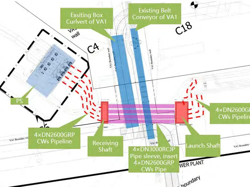
Pipe Jacking Project of Vietnam Vung Ang II power plant. Dự án thi công khoan đường ống nhà máy nhiệt điện Vung Ang II.
Xem thêm