JUNCTION INSTALLATION SURFACE DRILLING ĐÀ RIVER
The underground drilling through and various obstacles by underground drilling technique is more and more widely used around the world.
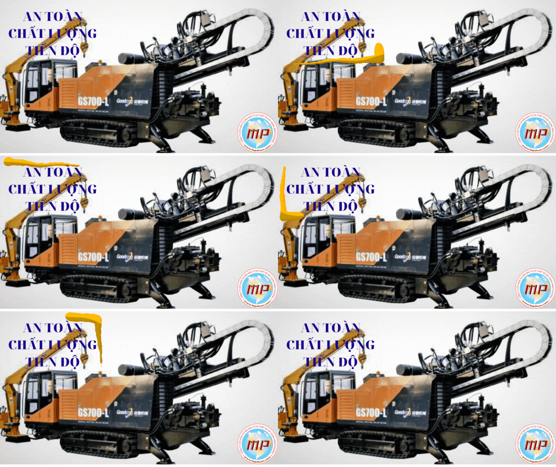
Underground drilling
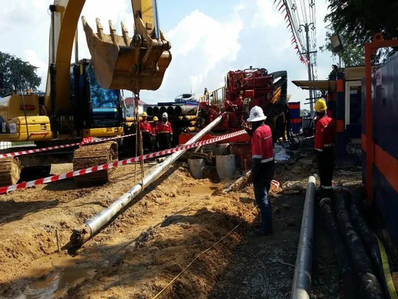
The underground drilling through and various obstacles by underground drilling technique is more and more widely used around the world. Underground drilling has the least operating environment compared to any tolerant method. Underground drilling technology also provides maximum coverage depth under obstacles, maximum protection and minimal maintenance costs. The river of traffic will not be disrupted, as most work is confined to either side of the river. Underground drilling has a short and predictable construction schedule and most importantly, underground drilling is in many cases less than other methods.
I. Underground drilling technique
1. Pilot hole
A pilot hole is initiated at a specified angle to the horizontal and continues under the obstacle along the design shape forming the line and providing a semi-long radius. Simultaneously with the pilot hole drilling, underground drilling companies can choose to run a larger diameter "wash pipe" that will surround the pilot drill line. The wash tube acts as a conductor sheath providing rigidity to smaller diameter pilot drill wires and will also save bore if it is necessary to retract the conductor to change bits. The guide is driven by a small bend in the drill wire immediately after cutting the tip. If the bend is oriented to the right, then the drill will proceed along a radial bend to the right. The drill line is monitored by an electronic package set up in the point test wire near the cutting head. Encapsulated electronics detect the chain system with the word earth and its inclination.
2. Headline
After having pilot hole, the hole must be widened so that the glass fits the pipe product. For example, if the pipe to be installed is 36 inches in diameter, the hole can be enlarged to 48 inches in diameter or larger. Briefly, the underground drill bit was attached to the drilling line on the shore facing the drill and back to the test hole. The connecting drill pipes are added when the drill bit returns to the drill. A large amount of sludge is pumped into the hole to keep the system alive and flush the windows.
3. Pull back
When the bore is enlarged, the pipe product can be pulled through it. The pipe is prefabricated on the face drill. The underground drill bit is attached to the drill wire, which is then connected to the towing end of the pipeline through a swivel joint. The rotation prevents the transition of the arrow into the spool allowing the pull to slide into the bore. Then, the underground drill rigs begins to work backwards, spinning and pulling the drill string and once again circulating large volumes of drilling mud. Foundation back to going to when the underground drilling and grounding pipeline at the underground drill rigs.
II. Layout and design
A. Access
Heavy equipment and underground drilling machine are required on both sides of the junction. To minimize costs, access should be provided to either side of the junction with the least distance from the finish line. Often the pipeline precedence is used and all satisfied usage rights must be provided by the owner. The Foundation of such satisfaction during the bidding process is impractical.
B. Not time working
1. Underground drilling rig
Minimum spread requires a maximum of 100 ft. 150 feet wide. Long area. This area should extend from the point away from the junction, although the entry point must be at least 10 ft inside the specified area. Since many components of an underground drill rigs are spread out without prepositioning, a underground drill rigs can be made up of unusually smaller areas. The operation is facilitated if the area is flat, stable and free of overhead obstructions. Puzzle activity that requires large amounts of water to sink. Nearby water source is needed.
2. Face tube
Sufficient length space work should be provided to make the pipe product into a chain. Width will be needed for normal pipe construction even though the workspace is 100 ft. 150 feet wide. Length should be provided at the main exit point. The length will ensure during redraw the pipe can be installed in an uninterrupted operation.
D. Information Technology
1. Depth of coating
After the underground drilling profile has been completed and the technical investigation is completed, the determination of the depth of the coating below the horizontal section will be carried out. Factors to be considered may include river flow characteristics, erosion depth due to periodic flooding, future expansion/deepening of the channel, and existence of existing pipeline or cable intersections. available at location. Typically, the minimum recommended depth of cover is 20 ft below the lowest part of the crossing. Although 20 ft. Is the recommended depth of cover on a river crossing, but crossing other obstacles may have different requirements.
2. Penetration angle and radius of curvature
Underground core drills with an entry angle of 8 to 20 can be used for most cross cuts. It is preferable for the straight tangent sections to be drilled underground before entering the long radius curve. The radius of the curve is determined by the bending characteristic of the product pipeline, increasing with diameter. The rule of thumb for a radius of curvature is 100 ft./1-in. diameter for steel pipe. The curve usually brings the cross-section to the elevation that provides the design shell of the underground pipeline.
E. Drilling survey
Most downhole surveyors are electronics that provide magnetic azimuth (for "right/left" control) and tilt (for "up/down" control). The surface locator can also be used in conjunction with the down hole electronics package.
1. Accuracy
The accuracy of the drill profile depends largely on variations in the earth's magnetic field. For example, large steel structures (bridges, conduits, other pipelines, etc.) and power transmission lines affect magnetic field readings. However, a reasonable drilling target at the pilot hole exit location is 10 ft. Left or right and -10 ft in length. To +30 ft.
2. Drawings during construction
Typically, survey calculations are performed every 30 ft during pilot hole operations. Drawings for underground drilling based on these calculations must be provided by underground drilling companies. Alternative methods such as gyroscopes, ground-penetrating radar or "smart" hogs can also be used to determine built-in locations.
III. Tube wrap
Coatings are used to provide a barrier against corrosion and wear. Directional crossings often encounter dissimilar materials and can often experience additional wear during return pullback. An external wear-resistant coating is usually warranted. To facilitate pipe backlash, the coating must bond well to the pipe to resist soil stress and have a smooth, hard surface to reduce friction and maintain a corrosion barrier.
Pipe Coating - The recommended pipe coating is fused bond epoxy (FBE). The minimum recommended thickness is 20 mils.
Joint Coating - Coating the weld area is the most important operation in the field to maintain a smooth wear-resistant pipe chain. It is recommended that the perimeter weld be coated with FBE powder using an induction heating coil and powder applicator to a minimum dry film thickness of 25 mils. As an alternative, two-component catalytic liquid epoxy can be applied to the circumferential weld area with a minimum dry film thickness of 25 mils using a paintbrush or roller. Tape should never be used for general coating on the pullback portion of a directional junction.
Learn more Pipe jacking auger method
CÔNG TY CP TƯ VẤN ĐẦU TƯ & THIẾT KẾ XÂY DỰNG MINH PHƯƠNG
Địa chỉ: Số 28B Mai Thị Lựu, Phường Đa Kao, Q.1, TPHCM
Hotline: 0903649782 - (028) 3514 6426
Email: nguyenthanhmp156@gmail.com

Xem thêm