Execution plan for horizontal directional drilling gas pipeline project
Execution plan for horizontal directional drilling gas pipeline project. This execution plan is proposed according to the work list which is provided by EPC as well as all the HDD geological condition are considered as the normal soil, and the HDD list is as followed.
Catalogue
3-1 Planed construction survey. 9
3-2 Construction Arrangement 9
3-2-2 Rig Configuration and Pull Force Calculation. 10
3-2-3 The configuration of construction. 12
3-2-5 Cooperation with pipeline construction unit 15
3-2-6 Cooperation with supervision unit 15
3-2-7 Cooperation with design unit 16
3-2-8 cooperation with nondestructive testing unit 16
3-3-1 Construction procedures. 17
3-3-2 Identification of HDD crossing length and location. 18
3-3-6 Installation of Fiber Optic Duct (FOC) Casing. 20
3-3-8 Safeguard measures to enlarge the hole. 21
3-3-9 Pipeline pulling methodology. 21
3-3-11 The measures to cross roads during pipeline back pulling. 22
3-3-12 The measures to ensure pipeline pullback smoothly. 23
3-3-13 Coating Protection measures during pipeline pullback. 24
3-3-14 Cuttings Treatment & Removal 24
3-3-15 The measures of crossing highways & streets in HDD.. 24
3-3-16 Construction measures along high voltage transmission lines. 25
3-3-17 Construction measures with existing parallel pipelines. 25
3-3-18 Post-Installation Testing. 25
3-4 Procurement and materials management 26
3-4-1 Materials’ Selection. 26
3-4-2 Manufacturers for primary materials purchased. 27
3-4-3 Measures for material receiving, inspection, storage and transportation. 27
3-4-5 Materials delivery hoisting and transport 29
3-4-7 Transportation of materials. 30
3-5-1 Emergency plan of drilling sticking. 30
3-6 -1 HSE managerial principles. 34
3-6 -2 HSE managerial targets. 34
3-6 -3 HSE management organization. 34
3-6 -4 Hazard identification, risk assessment, and control measures. 35
3-7 Schedule control measures. 38
3-7-3 Construction site management 40
3-7-4 Construction dispatching management 41
3-8-1 Quality Assurance System.. 42
3-8-2 Quality management organization. 42
3-8-3 HDD quality control elements. 43
3-8-4 Quality assurance measure. 43
3-9 Construction measures in rain season. 45
3-9-2 Inspection before rainy season. 45
3-9-3 Rain season construction equipment and material management 46
3-9-4 Rain season construction management 46
3-9-5 General measures for rain season construction. 46
3-9-6 Flood precautionary measures. 49
3-9-7 Considerations for rain season construction. 49
3-9-8 HSE Assurance Measures. 50
3-11 Construction area plan. 52
PERSONNEL EXPERIENCE RECORDS. 57
1. Company profile
MP COR. Engineering … is a professional company specializing in pipeline HDD and other pipeline construction. Persisting the core business of pipeline construction technology, emphasizing its high-level business, PCE develops its way of growing by implementing the HDD, Boring and other pipeline construction, integration of construction and service, integration of domestic and international markets.…..
2 Experience
In the past 10 years, our company has finished more than 200 HDD crossing projects, and the total length is more than 200 km. In 2017, our company as a subcontractor firstly entered into ….. gas pipeline project. So far, our company has participated and completed more than 20 Thailand pipeline construction projects, obtained excellent market reputation.
The follows are typical HDD experience- Some large diameter& long-distance HDD construction experience including geological conditions and detail of project.
|
…. HDD Project |
|
|
Owner |
|
|
Location |
|
|
Project Description (diameter, length, geological condition and detail of project) |
|
|
Commencement and completion date |
|
|
Rig Model |
|
|
… HDD Project |
|
|
Owner |
|
|
Location |
|
|
Project Description (diameter, length, geological condition and detail of project) |
|
|
Commencement and completion date |
|
|
Rig Model |
GD…/ Maximum Pullback force is 360T. |
|
…. HDD Project |
|
|
Owner |
|
|
Location |
|
|
Project Description |
|
|
Commencement and completion date |
|
|
Rig Model |
….GD450 Maximum Pullback force is 400T/300T/110T/45T. |
|
….HDD Project |
|
|
Owner |
|
|
Location |
|
|
Project Description |
|
|
Commencement and completion date |
|
|
Rig Model |
|
|
HDD Project |
|
|
Owner |
|
|
Location |
|
|
Project Description |
|
|
Commencement and completion date |
|
|
Rig Model |
…/GD450 Maximum Pullback force are 600T/ 220T/ 110T/ 45T. |
|
…… HDD Project |
|
|
Owner |
|
|
Location |
|
|
Project Description |
|
|
Commencement and completion date |
2024.08- now |
|
Rig Model |
., Maximum Pullback force is 600T |
3 Plan of Execution
3-1 Planed construction survey
This execution plan is proposed according to the work list which is provided by EPC as well as all the HDD geological condition are considered as the normal soil, and the HDD list is as followed.
|
No. |
Location |
KP |
Obstacles DEPTH (m) |
Length(m) |
|
H01 |
Xeo ro Canal |
KP16+110 |
-5.6 |
361.5 |
|
H02 |
Cai Lon River |
KP30+500 |
-10 |
971.3 |
|
H03 |
Cai Be River |
KP35+950 |
-8.5 |
576.6 |
|
H04 |
National Road No 61 |
KP39+620 |
|
256.2 |
|
H05 |
Thot Not Canal |
KP58+240 |
-6.5 |
354.5 |
|
H06 |
National Road No 91 |
KP97+180 |
|
237.5 |
3-2 Construction Arrangement
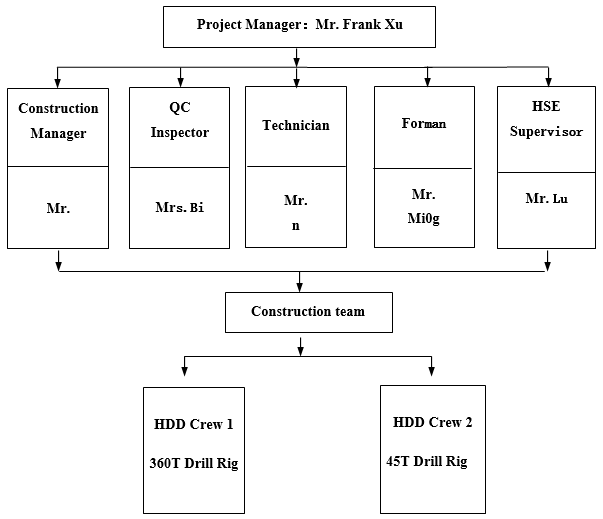
3-2-1 Organizational Chart
3-2-2 Rig Configuration and Pull Force Calculation
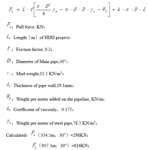
The following calculation combined with the HDD construction experience is based on the two typical HDD projects selected respectively from the HDD work list. And H02#, 971.3 meters in length with the diameter of 30 inches. H04#, 354.5 meters in length with the diameter of 30 inches. The calculation is as follows.
Pull force calculation
Pull force calculation table
|
No. |
Location (KP) |
Pipe size/mm |
Length/m |
Max. Pull force/KN |
|
H01 |
KP15+800 |
762 |
330 |
304 |
|
H02 |
KP31+348 |
762 |
940 |
816 |
|
H03 |
KP35+804 |
762 |
549 |
485 |
|
H04 |
KP39+541 |
762 |
217 |
215 |
|
H05 |
KP58+000 |
762 |
325 |
298 |
|
H06 |
KP97+403 |
762 |
182 |
200 |
The maximum pull force calculated of H02# is 816 KN which had been multiplied by the safety factor of 1.5. As well, the maximum pull force calculated of H05# is 298 KN which had been multiplied by the safety factor of 1.5.
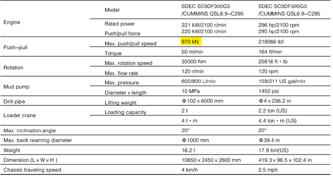
In order to finish all the HDD projects, one XZ3600 rig (maximum pullback force is 360 tons), one XZ960E rig (maximum pullback force is 96 tons), will be put into this project.
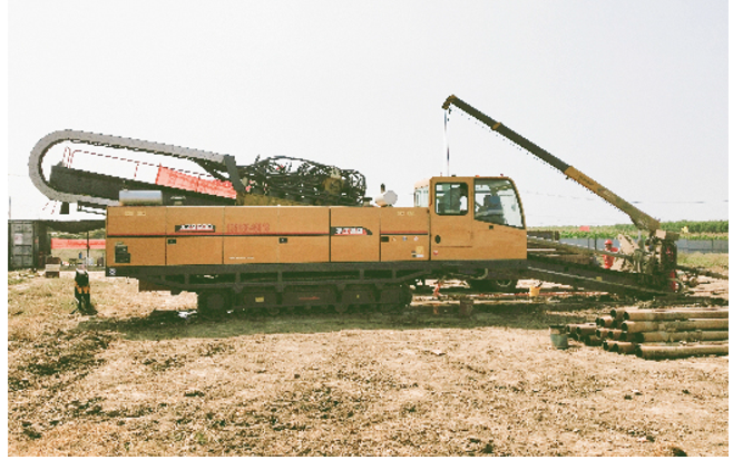
Rig technical parameter of XZ3600
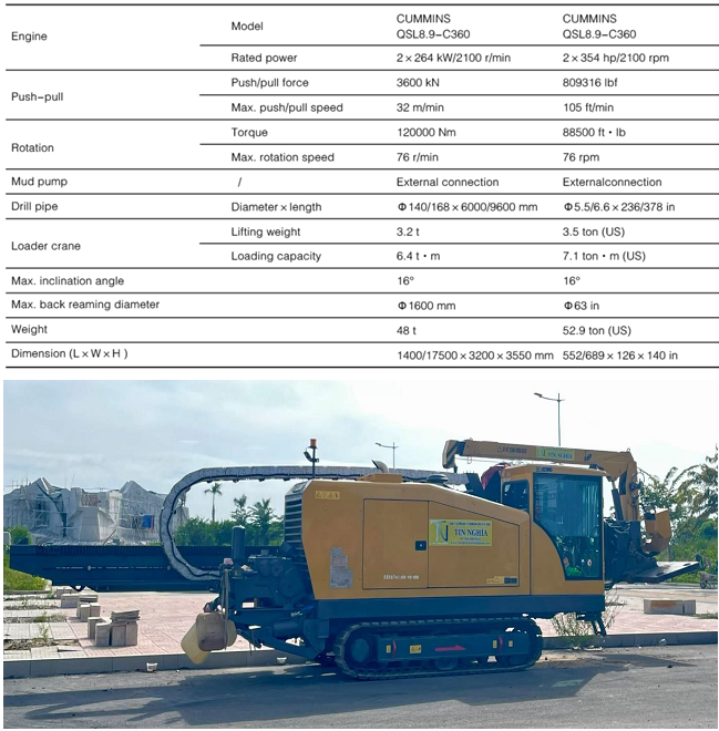
Rig technical parameter of XZ960E
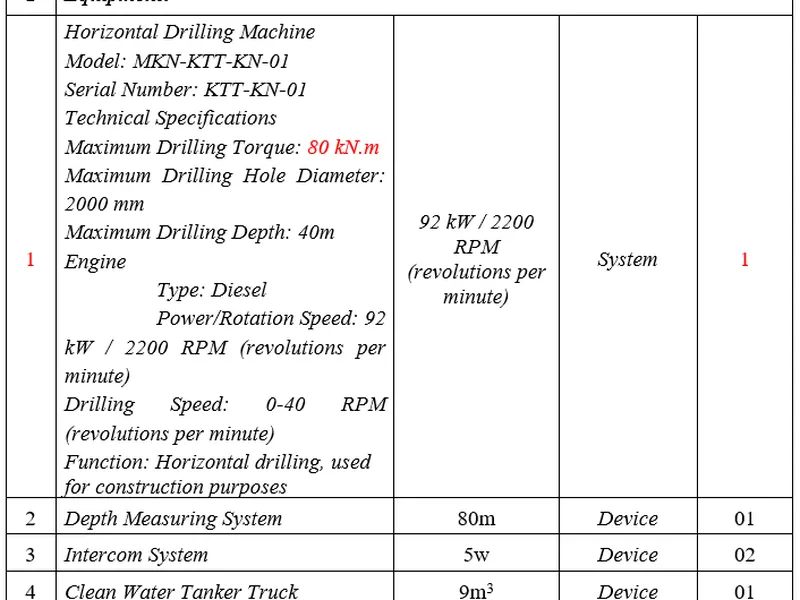
3-2-3 The configuration of construction
Key equipment table
GD6000-LL Dril Rig &Key Equipments
|
No. |
Equipment |
Model |
Set |
Manufacturer |
Ownership |
|
1 |
Rig |
XZ3600 |
1 |
XCMG |
Own |
|
2 |
Generator |
200KW |
1 |
N/A |
Own |
|
3 |
Generator |
100KW |
1 |
N/A |
Own |
|
4 |
Mud Pump |
1m³ |
1 |
N/A |
Own |
|
5 |
Mud Tank |
18m³ |
2 |
N/A |
Own |
|
6 |
Storage Tank |
20m³ |
1 |
N/A |
Own |
|
7 |
CSQ300×2 |
2 |
N/A |
Own |
|
|
8 |
Excavator |
CAT320 |
1 |
|
Rent |
|
9 |
Tank Truck |
10m³ |
1 |
|
Rent |
|
10 |
Vacuum pump car |
6m³ |
1 |
|
Rent |
|
11 |
Flat bed trailer |
13m |
1 |
|
Rent |
|
12 |
Drill pipe |
5-1/2″ |
200 |
Made in China |
Own |
|
13 |
Pick-up |
5 seats |
1 |
|
Rent |
|
14 |
Minibus |
11 seats |
1 |
|
Rent |
|
15 |
Crane |
25T |
1 |
|
Rent |
XZ960E Dril Rig &Key Equipments
|
No. |
Equipment |
Model |
Set |
Manufacturer |
Ownership |
|
1 |
Rig |
XZ960E |
1 |
XCMG |
Own |
|
2 |
Generator |
100KW |
1 |
N/A |
Own |
|
3 |
Generator |
100KW |
1 |
N/A |
Own |
|
4 |
Mud Pump |
0.6m³ |
1 |
With Rig |
Own |
|
5 |
Mud Tank |
10m³ |
1 |
N/A |
Own |
|
6 |
Storage Tank |
10m³ |
1 |
N/A |
Own |
|
7 |
CSQ300×2 |
1 |
N/A |
Own |
|
|
8 |
Excavator |
PC150 |
1 |
|
Rent |
|
9 |
Vacuum pump car |
6m³ |
1 |
|
Rent |
|
10 |
Flat bed trailer |
13m |
1 |
|
Rent |
|
11 |
Drill pipe |
4-1/2″ |
100 |
Made in China |
Own |
|
12 |
Pick-up |
5 seats |
1 |
|
Rent |
|
13 |
Minibus |
11 seats |
1 |
|
Rent |
|
14 |
Crane |
15T |
1 |
|
Rent |
Personnel Arragement-HDD Crew1 Arrangement
|
No. |
Profession |
Quantity |
No. |
Profession |
Quantity |
|
1 |
HDD Supervisor |
1 |
10 |
Excavator operator |
1 |
|
2 |
Driller |
1 |
11 |
Driver of Mud-tank truck |
1 |
|
3 |
Steerer |
1 |
12 |
Driver of water-tank truck |
1 |
|
4 |
Mudman |
1 |
13 |
Driver of vacuum pump car |
1 |
|
5 |
Drill pipe operator |
1 |
14 |
Driver of flat bed trailer |
1 |
|
6 |
Electrician |
1 |
15 |
Interpreter |
1 |
|
7 |
Maintenance man |
1 |
16 |
Driver of minibus |
1 |
|
8 |
Labor |
4 |
17 |
Operator of Crane |
1 |
|
Subtoatal |
12 |
Subtoatal |
8 |
||
|
Total |
20 |
||||
Personnel Arragement-HDD Crew2 Arrangement
|
No. |
Profession |
Quantity |
No. |
Profession |
Quantity |
|
1 |
HDD Supervisor |
1 |
10 |
Excavator operator |
1 |
|
2 |
Driller |
1 |
11 |
Driver of Mud-tank truck |
1 |
|
3 |
Steerer |
N/A |
12 |
Driver of water-tank truck |
1 |
|
4 |
Mudman |
1 |
13 |
Driver of flat bed trailer |
N/A |
|
5 |
Drill pipe operator |
N/A |
14 |
Interpreter |
1 |
|
6 |
Electrician |
1 |
15 |
Driver of minibus |
1 |
|
7 |
Maintenance man |
N/A |
16 |
Operator of Crane |
1 |
|
8 |
Labor |
4 |
17 |
|
|
|
Subtoatal |
8 |
Subtoatal |
6 |
||
|
Total |
14 |
||||
3-2-4 Interface management
It is inevitable to interact with other contractors such as pipe prefabriaction manufacturer and supervision unit during the project period. Dealing with the cross construction and relation coordination with other units, we should adhere to the following principles: First, every contractor shoud maintain a sense of overall situation, and put the interests of the project at first place, emphasizing on the progress, quality and safety of construction and avoiding preoccupying in trivial matters. Second, the working interface of each contractor shoud be confirmed in advance and the interactive coomunication should be enhanced.
3-2-5 Cooperation with pipeline construction unit
We will provide pipeline construction unit with accurate location of entry point and exit point and share the access road as much as possible, cooperating closely to ensure the successful completion of pulling, after which we will handle site slurry properly and offer detailed crossing data to creat favorable condition for pipeline unit to proceed work like connecting pipes.
3-2-6 Cooperation with supervision unit
We will fully respect supervivion unit and comply to the instructions from supervisor and owner, contrling working progress strictly, enhancing material management, strenthening construction management, intensifying safty and quality awareness and executing with civilization.
3-2-7 Cooperation with design unit
1 Soil data topography and bathymetrical survey will be done by the design company. The construction drawings will be designed and submitted for EPC approval, and the profile will be crossed according to the approved drawing.
2 When the design is not achievable, the design unit should be informed immediately to survey the site and work out practic construction design together.
3 The usage amount and attrition rate of owner supplied and contractor purchased material need to be confirmed in cooperation with design unit to ensure the accuracy of specification,model and quantity of materials.
4 The regulated construction process and technique should be strictly followed to meet the demand of construction design.
5 If the design alteration occurs, the new technique requirements and construction method should be followed.
6 After the completion of project, the detailed and accurate as-built surveying report accordance with the important design documents like design and construction alteration is required.
3-2-8 cooperation with nondestructive testing unit
1 The construction should be properly arranged to ensure there is no interference between site work and testing.
2 If necessay, the support for testing is required by personnel and equipment at site.
3 For the pulling construction of multiple to one, the owner and testing unit should be notified the testing of welding seam in advance and standby on call for timely testing and results to shorten the pause period during pulling.
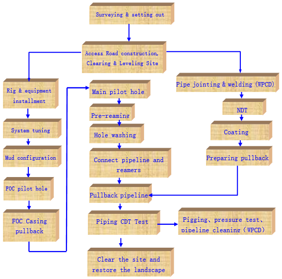
3-3 Construction scheme
3-3-1 Construction procedures
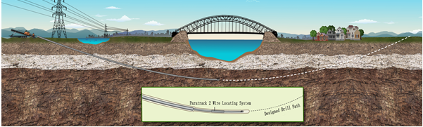
3-3-2 Identification of HDD crossing length and location
In this program, there are roads or country roads which can facilitate the entrance and exit of the equipment in most of HDD entry points, but when entering the construction site, several individual projects need to build access road in the ROW.
The rig1 site is aroud 20m × 70m, and the rig2 site is aroud 15m × 50m. Make sure the road without water, and meet the safety construction requirements. Ensure the road can sustain the heavy equipment, such as rig, power station, mud pump and other large vehicles.
The rig1 exit site is aroud 15m × 40m, and the rig2 exit site is aroud 10m × 35m. Make sure the road without water, and meet the safety construction requirements. It is necessary to take up the driveway when construction along the highway and use concrete barriers to isolate the site and protect workers and equipment.
3-3-3 RIG ANCHOR
Prior to installation of the rig anchor, all services will be located and clearly marked and/or protected; the procedure for the protection of these services will be site specific and so will be covered in the relevant Site-Specific Construction Procedure for each crossing. The rig anchor will be a sheet pile, or concrete block design. Design of the structure is site specific and engineering will be detailed in the relevant Site-Specific Construction Procedure for each crossing.
3-3-4 Drilling Fluid
The drilling fluid and any additives that will be used for the crossings shall be based on site-specific requirements. The soil investigation data will be used to determine the expected formation and most suitable mud program.
Generally, the mud used for the project will consist of water (more than 90%) plus natural clay, also referred to as bentonite and water will be directed to the rig site by trucks or pumped from an approved local water source and mixed with the bentonite. Small quantities of additives may be used to improve the properties of the mud to suit the ground conditions encountered. However all materials used in the mud, including the bentonite shall be environmentally harmless. Material Safety Data Sheet (MSDS) for each additive will be available for on-site inspection.
After mixing and when the mud is at the correct viscosity and quality for the prevailing drilling conditions, it will be pumped from the mix tank to the active tank and then via the mud pump to the drill string and down hole. The drill fluid will return to surface via the annulus carrying the cuttings with it. In order to reduce the total volume used, the mud will be cleaned and recycled where possible; therefore a recycling installation consisting of shale shakers and centrifuges and sand cleaner will be installed on site. The mud surfacing at the exit side will be pumped to rig side, through the FOC duct. On the longer crossings, an additional pipe side recycling system and displacement pump may be employed.
3-3-5 Pilot Hole
Pilot-hole drilling is the first stage in the drill process. The pilot drill string will be advanced along the engineered and approved path from the entry surface location to the exit surface location. The hole for FOC duct will be drilled first and the hole for the 30” carrier pipe after that. If the design is mailine and FOC are installed in one borehole, the pilot hole will be drilled one time.
Size and type of the bit will be determined to suit the ground conditions. As the string is advanced the action of bentonite being pumped down the string and through the bit erodes the soil formation. The bit is steered by means of an offset sub behind the jet bit. The string is rotated depending on the design profile and the ongoing survey data. A down-hole mud motor will be used if conditions require for hard ground conditions.
At the completion of the pilot-hole drilling, tabulation sheets of co-ordinates, length, depth, inclination, azimuth and drawing, which accurately describe the location of the pilot hole, will be submitted to EPC.
The drilling tools of rig1 used in the pilot hole drilling is:
91/2″steel-tooth bit(soil layer)+ Deflecting sub+ non-magnetic drill collar+5” drill pipes, or
91/2″roller bit(rock or hard sand layer)+ mud motor-bent sub + non-magnetic drill collar+5-1/2″ drill pipes.
The drilling tools of rig2 used in the pilot hole drilling is:
8-1/2″ normal soil bit (soil layer) +4-1/2” drill pipes
3-3-6 Installation of Fiber Optic Duct (FOC) Casing
The fiber optic duct casing will be installed prior to the installation of the 30″mainline. The duct casing may be drilled and installed utilizing a smaller capacity rig together with a walkover locating system if conditions allow. A flange will be welded to the ends of the FOC casing both exit side and entry side and connected directly to the return pump on pipe side. The duct casing will be used as a mud return line during reaming operations and will be flushed and capped prior to demobilization.
The assembly of drilling tools for pulling FOC Casing is:drill pipe + cardan joint + head of pullback + cable casing.
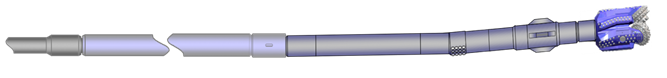
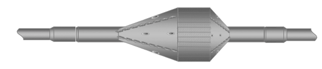
3-3-7 Reaming
After the drill bit is excavated, remove the drill tool and connect the reamer. Spray the hole in front of the hole to check if the nozzle is clear.
According to the construction experiences and the combination of geological survey report, 30 "pipe is used for the 4-step reaming +2 washing hole if normal soil condition (which can increase the numbers of enlarging and washing holes depends on actual situation). Choose 5 " drill pipe: each hole is used for the backflow of the drill pipes.
The assembly of drilling tools in 30" Directional drilling and reaming (soil)
|
NO. |
Procedure |
Drilling tools |
|
1 |
Level 1 reaming |
5-1/2″ drill pipe+Ф500mm Spiral reamer +5-1/2″ drill pipe |
|
2 |
Level 2 reaming |
5-1/2″ drill pipe +Ф800mm Spiral reamer +5-1/2″ drill pipe |
|
3 |
Hole washing |
5-1/2″ drill pipe +Ф700mm Barrel reamer +5-1/2″ drill pipe |
|
4 |
Level 3 reaming |
5-1/2″ drill pipe +Ф962mm Spiral reamer +5-1/2″ drill pipe |
|
5 |
Level 4 reaming |
5-1/2″ drill pipe +Ф1016mm Spiral reamer +5-1/2″ drill pipe |
|
6 |
Hole washing |
5-1/2″ drill pipe +Ф962mm Barrel reamer +5-1/2″ drill pipe |
- In the construction of each step, it is important to observe the reaming process. If the hole is not smooth, it should be cleaned.
(3) It is reasonable to choose the reamer size, nozzle size and nozzle quantity for the next hole-reaming process based on the geological conditions and the situation of last hole-reaming process, and to improve the carrying capacity of mud by controlling the mud pressure and flow rate.
3-3-8 Safeguard measures to enlarge the hole
a) When the pilot hole completed, the drill bit and the non-magnetic drill collar should be removed in time. Then Install the reamer for the pre-expansion hole.
b) To improve the mud displacement according to the design requirements, and make sure the reaming process is smoothly. It is strictly prohibited to pump mud in a suppressed pressure, to enlarge the hole with a extra large torque, or to enlarge the hole by violence. Operators should pay attention to the pump pressure, torque as well as the changes of pull force.
C) When reaming and washing holes, make sure that the mud viscosity to protect the hole wall from collapsing.
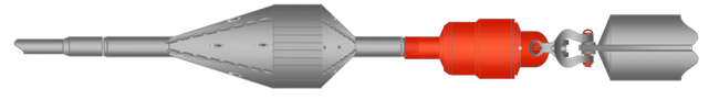
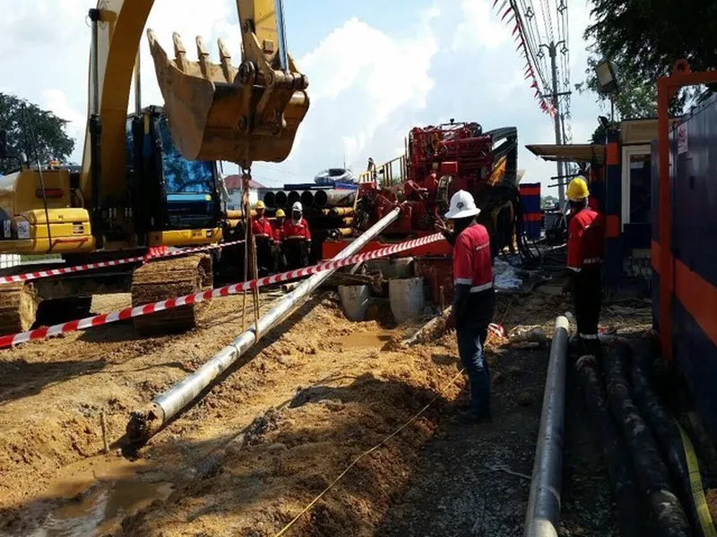
3-3-9 Pipeline pulling methodology
Pipe rollers will be laid between the end of the string and the HDD exit point. The pipe string will be pulled along rollers to exit point-using excavators. A barrel reamer and swivel assembly will be attached to the pulling head and the rig will take up the tension. The pipe string will be lifted into the overbend position by cranes and excavators as the pipe string is pulled into the drilled hole. Pipe pulling will continue to completion.
During pullback operations the pipe string will be monitored by a Pipeline Supervisor to prevent potential damage to the coating from coming into contact with rollers or other objects. Personnel with radios will be positioned at intervals along the pipe string with contact to the rig to stop pullback if required. To avoid miss-communication the HDD Supervisor will be the single source of communication to the driller. Personnel will be positioned at intervals along the pipe to watch for any misaligned rollers and potential problems. Pipeline personnel will receive proper instruction prior to pullback as to how to signal the supervisor with radios to halt pulling if there is a potential problem. Adequate lighting will be provided for night operations and positioned so as not to disturb road users and general public.
Piping back to the assembly: 5-1/2″ drill pipe +Φ813mm barrel reamer + 150T transfer + u-shaped ring + 30 " pipeline
3-3-10 Mud displacement
1) Several large mud pumps will be put into use in this project. The mud displacement can reach 1000L/min by GN1000 mud pumps for the rig1. The mud displacement can reach 600L/min the own mud pumps for the rig2.
2) Mud displacement in soil HDD construction project: 500-1000L/min depends on the HDD length and soil condition.
3-3-11 The measures to cross roads during pipeline back pulling
If there are prefabricated pipeline crossing roads during pipeline back pulling, some general measures described as the following should be used to solve the problem.
- Set up warning signs in advance, and arrange standard bearer to direct traffic in order to avoid traffic accidents。
- The way of lifting pipeline is used to cross the highway and the traffic will be temporarily closed under this situation。
- Install a high limit bar over the highway entrance and a specially-assigned man will direct the large vehicles to make a detour.
3-3-12 The measures to ensure pipeline pullback smoothly
- Make sure the pilot hole as smooth as possible and meet the requirement of design, and avoid S-shaped curve.
- Overall maintenance to key machinery and equipment will be executed before the final reaming holes (hole washing). Another systematically checking will be executed before the pipeline pullback to make sure all the machinery and equipment are perfect.
- Set out to prepare the pulling work as early as possible. After the preparatory work, hole cleaning will be executed one more time again. Try best to avoid long time delay, otherwise,another hole cleaning maybe become necessary.
- Adjust the pipeline’s position, and make sure its angle is consistent with the exit angle. Take some steps to make sure the pipeline straight and avoid the problem caused by huge bending. It is an efficient way to open cut a ditch of 10 meters in length along the crossing direction. And then the pipeline pullback process will become easier.
- By adjusting the mud property, it can improve the capacity of slurry suspension, carrying, lubrication, cementing and plugging. When increasing the polymer proportion in the mud, its suspension and cementing capacity can be improved. Adding rheological agent into mud can maintain its fluidity with a high viscosity, improve its carrying capacity and reduce the viscous force. Adding lubricant into mud can reduce friction and also it is benefit to isolating the sand layer.
F) Pipeline pullback process should be continuously. Stoppage should be avoided. Check the connection situation of rotating joint, U-shackles, reamer, make sure everything is perfect before pulling. The driller must keep communication with patrols during pipeline pulling process, and make sure the pipeline can be installed on the designed position.
3-3-13 Coating Protection measures during pipeline pullback
- The corrosion protection operator and driller should cooperate with each other during the pipeline pullback process. If there are any damages founded on the pipeline repairing must be done immediately. The patrols should find out the reason and solve it. This task should be executed through the whole pullback process.
- After finishing the pipeline anticorrision, the outside of the pipeline should be protected to avoid damage during pullback process.
- Pile up the bentonite bags to lift the pipe-roller away from the ground if the site is no enough space and make sure the pipeline can not reach the ground directly. Through this way we can reduce the contact area between pipeline and ground and can protect the pipeline efficiently.
- In the pipeline pullback process, the mud must meet the requirement, match with the geological conditions, and can improve the smoothness of enlarged hole. The enlarged hole must be filled with mud. Keep the pipeline to be in suspending in the enlarged hole. This way can reduce the friction between pipe and hole wall, and can prevent the pipe to be damaged.
- Check the insulating property of the pipeline and the connection situation between drilling tools before the pipeline pullback. Start pulling when everything is perfect
3-3-14 Cuttings Treatment & Removal
During pull back of the pipeline, a volume of mud equal to the volume of the pipe will be displaced. This will be stored on site using pits where possible and/or removed to an approved dumpsite via trucks. The type of mud storage will be indicated on the site lay out drawing in the site-specific procedures, which will be used to obtain all necessary permits. Cuttings produced during the drilling process will be removed to an approved local dumpsite.
3-3-15 The measures of crossing highways & streets in HDD
If there are some of the HDD projects parallelling with the road and street, it should be very important to adopt safeguard measures at this section. Due to limited space, emergency lane maybe used when construction. Concrete barrels used to isolate the site and warning lamps will be necessary for safety protection. In order to avoid traffic accidents, one standard-bearer standing at the site entrance will be assigned to direct the traffic.
3-3-16 Construction measures along high voltage transmission lines
The high voltage transmission line is too high to influence the site work. For the absolute safety reason we will use PⅡ steering system in this project. Safety signs will be set at the construction site. It is forbidden that standing close to the high voltage transmission line or climbing the power tower. Detailed technical and HSE disclosure will be executed at site before construction.
3-3-17 Construction measures with existing parallel pipelines
If there was parallel pipeline, the followed method will be executed.
1) Analyze the data of the established pipeline provided by the Owner, and the data must be accurate.
2) In order to plan the route of this new pipeline, the route of established pipelines should be marked based on the drawings.
3) In order to get accurate data, a large magnetic coil should be established and P Ⅱ steering system should be used as well.
4)In order to protect the established pipeline, and determine the drilling depth of the HDD construction project, technicians should depend on the data of the established pipeline supplied by the Owner.
5)If the established pipeline is close to the new pipeline, firstly we will apply to EPC for excavating it out. Further protection, such as isolation with steel plate will be adopted if necessary after excavation work finished.
3-3-18 Post-Installation Testing
The carrier pipe shall be pre-tested as a single string, unless approved otherwise, ex-situ prior to application of field joint coating.
Subsequent to installation of the crossing, the crossing section shall be hydrostatically tested again. Gauging shall be carried out by using gauging pig equipped with a gauge plate. The aluminum gauge plate diameter shall be equal to 95% of inside diameter of the heaviest wall pipe in the test section. Compressed air or hydro water shall be used to run Gauging pig. After receipt of gauging pig at the other end, the gauge plate shall be inspected in the presence of EPC’s Representative. A deformed, bent or severally nicked plate or damaged pig shall be evidence of gauging pig run failure and the same is not acceptable to Company. In such cases, the Contractor shall locate any obstruction and/or faults such as dents, buckles, flat spots, etc. and rectify the same to the satisfaction of the EPC’s Representative. A written approval shall be obtained from EPC’s Representative regarding successful completion of gauging pig run. After acceptance of gauging run, water filling shall commence.
The test pressure shall be 1.5-time design pressure adopted during pre-testing. After stabilization of the temperature, the pressure shall be maintained for a period of 24 hours. No unaccountable pressure drop shall occur after isolation the test section from the pressurizing system.
3-4 Procurement and materials management
We agree to purchase materials from suppliers designated by the contractor and to continue to purchase the materials required for long-term supply in the project; Responsible for the procurement process designated and agreed by the contractor; We are responsible for receiving, shipping and storing materials and equipment, and protecting the equipment from damage according to the supplier's instructions. All materials and equipment should be stored in enclosed warehouses except for owners/consultants and contractors.
3-4-1 Materials’ Selection
Procurement document formulation
- The purchaser shall prepare material purchase documents according to the design material list, change order, budget material and material application plan.
- The material purchasing documents shall list the quality requirements, and the reference number of the existing standard shall be listed in addition to the name, specification, model, material, quantity and delivery date.
- The purchase of materials with special technical requirements must have clear acceptance standards to ensure that the supply contract and technical agreement can meet the quality, quantity and delivery requirements of the materials.
- The content of material purchase documents must be complete and approved by the project manager after reviewed by the procurement manager.
- Additional Materials
Contractor may request the Subcontractor to procure additional items of material or equipment not required for the Work under the Scope of Work during the execution of the Subcontract. The Subcontractor shall procure such items, arrange for necessary inspection and deliver the items to Contractor.
3-4-2 Manufacturers for primary materials purchased
Regarding the manufacturers of primary materials purchased by the third Party, according to the standard specification and design requirements, select the manufacturer whose materials are much more reliable quality than others.
According to past experience of construction, generally the principle of purchasing from local is prior to be adopted and select excellent local manufacturers as the project raw material supplier.
According to the specific requirements of this project on the material, the investigation on local market for material supply has been conducted, if the project is awarded, in accordance with the relevant provisions for the administration of project owner, the pruchasing tendering will be executed to ensure the quality of materials to meet the requirements of the owner.
3-4-3 Measures for material receiving, inspection, storage and transportation
In order to ensure materials and equipment quality in good condition for horizontal directional drilling construction in the process of receiving, inspection, storage and transport, the relevant operation processes for each stage must be in strict accordance with the measures of implementation, at the same time contractor self-purchasing material still shall implement the provisions of the relevant documents issued by project owner.
General provisions:
- The procurement department of the construction unit shall be responsible for the receiving, inspection, storage and transport of materials and equipment used for the project.
- All materials used for the project must be inspected and qualified to be accepted and used, and the records for materials inspection and acceptance shall be filled in detail.
- When material reinspection is required, the sampling and reinspection shall be responsibled by designated personnel and the approval by project owner shall be required before reinspection. The reinspection shall be authorized to the special institutes that has the related qualifications that approved by national authority or industry associate for doing such job.
- All kinds of measuring instruments shall be checked, verificated and calibrated by national metrological verification departments or authorized institutions and shall be used within the validity period.
- In respect to unqualified products that were found when doing inspection, acceptance and reinspection, the contractor shall refuse to receive them.
3-4-4 Materials management
- All materials used in the project must be inspected and qualified to be admitted to the warehouse, otherwise they cannot be put into use or processed.
- The storage of materials shall be kept in accordance with the procedures for the custody of materials and materials.
- After the materials have been inspected and qualified, the quality inspection personnel shall sign for arrival goods in the notification and acceptance records, and the qualified products shall be put into the qualified zone by the warehouse keeper.
- Unqualified materials are tested and the custodian fills out the notice of rejection (for processing) and puts unqualified products into the unqualified zone.The purchaser shall contact the supplier to solve and deal with the defective products in time.
- In the inspection of material quantity, the materials that are in short supply or overflow are found. In addition to actually filling out the records, they shall be stored separately, properly kept, and prevent from being mixed and wait for being processed.
3-4-5 Materials delivery hoisting and transport
- Material delivery
- After the material distribution vouchers are checked and confirmed without mistakes, adhering to the principle of " first in,first out", material distribution follows the procedure like that first taking stock checking, second singing and moving material, third distributing material and last taking quad-check.
- When the materials are sent, the corresponding technical quality certificates and certificates will be transferred.
- All outgoing materials shall be quality conformance, right quantity, finished procedure and complete documents.
3-4-6 Material hoisting
- The weight of lifting parts must be mastered before hoisting, and the lifting and rigging should be carefully checked to ensure the safety factor.
- A special person is required to conduct the loading and unloading of pipes when the lorry-mounted crane was used.
- Use special hooks for protection of damaged pipe and handling. The box body should have the reinforcement measures to prevent the deformation of the hoisting, ensure that the equipment in the hoisting is not damaged by external forces.
- During lifting process, the steel tube and wire of more than 30 ° in angle, the pipe ends shall be set traction rope make accurate discharge pipe.
- When lifting and discharging the pipe, the lifting and discharging should be lifted gently to avoid the collision with other objects or pipes, and it is strictly prohibited to use crowbar roller to unload from trailer.
- For large equipment that cannot be containable, it should be convenient to transport equipment base and fixed point, and identify the center of gravity or lifting point.
3-4-7 Transportation of materials
1) Equipment, small pieces and vulnerable parts shall be packed in outer packing, and the packaging shall be kept in good condition when transported.
2) The spare parts to be shipped with the equipment shall be packed and fixed in case of loss.
3) The packaging should be marked clearly, with clear and easy identification, such as orientation, anti-impact, moisture-proof, waterproofing and lifting point.
4) The equipment should be fixed with wire rope or reverse chain, with wooden block, wedge and other anti-slip.
5) Before hoisting, transporting equipment and piping, check the impact of passing road conditions and the presence of high voltage and communication lines along the way, and make preventive measures in advance.
6) The route of transportation should be the route with good road conditions, flat and broad pavement, and meet the road requirements about loading weight and " over three limits"(Length, Width and Height).
7) When the goods are transported with exceeding the height, length, width limitations or on restricted road section, they should apply to the local traffic management authority for getting pass approval of " over three limits " and "road pass peimit" before the truck going on road.
>>> SEE MORE: Construction Method for Horizontal Directional Drilling (HDD) of the Gas Pipeline
CÔNG TY CP TƯ VẤN ĐẦU TƯ & THIẾT KẾ XÂY DỰNG MINH PHƯƠNG
Địa chỉ: Số 28B Mai Thị Lựu, Phường Đa Kao, Q.1, TPHCM
Hotline: 0903649782 - (028) 3514 6426
Email: nguyenthanhmp156@gmail.com
Tin tức liên quan
1036 Lượt xem
The purpose of this document is to provide the methodology for the Contractor to execute and control the HDD drilling works across roads and canals, and the pulling of 16” steel pipes inside 20” steel casing pipes, under the Project “Fuel Pipeline System for Aircraft from the Upstream Port to Long Thanh International Airport.”
2189 Lượt xem
This purpose of this document is to describe in general terms the HDD process and methodologies that will be utilized for “Approximately 94 km of 30-inch onshore pipeline from An Minh Landfall Station to O Mon Gas Distribution Center (GDC) at Can Tho Province” section this project.
1449 Lượt xem
Construction Method for Horizontal Directional Drilling (HDD) of the Gas Pipeline. Present the horizontal directional drilling method for the project, general construction organization methods, on-site construction organization, construction site layout, quality control measures, applicable technical standards, and construction sequence.
1760 Lượt xem
The purpose of this document is to propose a method for the Project Management Consultant and the Investor to review and approve for the Contractor to execute and control the drilling process for pulling a steel pipe with a diameter of D200 under the road.
6186 Lượt xem
This document has been prepared to describe the methodology by which MCD/HDDT propose undertaking the site preparation, mobilization, drilling operations, pipe installation, pre-commissioning and reinstatement operations for the installation of the 6 HDD crossings on the Block B Omon Project - Onshore Pipeline.
2332 Lượt xem
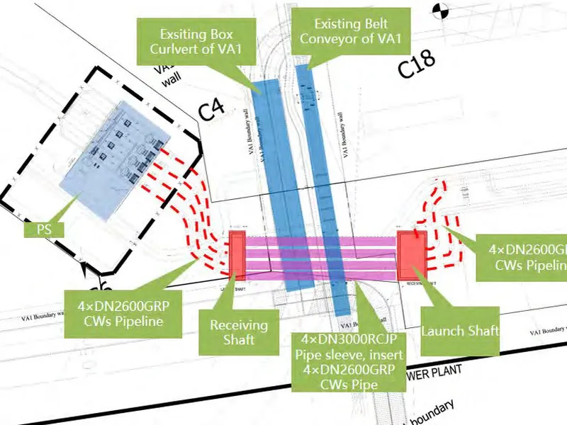
Pipe Jacking Project of Vietnam Vung Ang II power plant. Dự án thi công khoan đường ống nhà máy nhiệt điện Vung Ang II.
Xem thêm