Construction Method for Horizontal Directional Drilling (HDD) of the Gas Pipeline
Construction Method for Horizontal Directional Drilling (HDD) of the Gas Pipeline. Present the horizontal directional drilling method for the project, general construction organization methods, on-site construction organization, construction site layout, quality control measures, applicable technical standards, and construction sequence.
PROJECT NAME: BLOCK B - O MON GAS PIPELINE PROJECT
PACKAGE: HORIZONTAL DIRECTIONAL DRILLING (HDD) SERVICE
EMPLOYER: SOUTHWEST PIPELINE OPERATING COMPANY (SWPOC)
CONTRACTOR: PETROVIETNAM TECHNICAL SERVICES CORPORATION
SUBCONTRACTOR: PTSC THANH HOA – MINH PHUONG – PCE CONSORTIUM
1. GENERAL INTRODUCTION
1.1. Project Description
PROJECT NAME: BLOCK B - O MON GAS PIPELINE PROJECT
EMPLOYER: SOUTHWEST PIPELINE OPERATING COMPANY (SWPOC)
CONTRACTOR: PETROVIETNAM TECHNICAL SERVICES CORPORATION
South West Pipeline Operating Company (SWPOC) hereafter referred to as COMPANY is responsible for development of Block B-O Mon Gas Pipeline to transport natural gas from Block B, 48/95 & 52/97 located in Southwest Sea of Vietnam to supply gas to the power plants at O Mon Power Centre, supplement gas for Ca Mau Gas – Power- Fertilizer Complex and other customers at Southwest area. The overall project includes about 431.69 km of offshore and onshore gas pipelines passing through 03 provinces/cities including Ca Mau, Kien Giang and Can Tho.

The Block B-O Mon Gas Pipeline Project includes the following facilities:
The offshore pipeline has a total length of 330.69 km, of which:
+ Approximately 292.24 km of 28-inch offshore pipeline from Subsea Isolation Valve (SSIV) downstream flange to An Minh Landfall Point (LFP) at Kien Giang province;
+ Approximately 38.45 km of 18-inch spur offshore pipeline from KP 206.9 to approach Mui Tram Landfall Station (LFS) at Ca Mau province. The onshore pipeline has a total length of 102.8 km, of which:
+ Approximately 7 km of 28-inch onshore pipeline from An Minh Landfall Point to An Minh Landfall Station (LFS) at Kien Giang province;
+ Approximately 94 km of 30-inch onshore pipeline from An Minh Landfall Station to O Mon Gas Distribution Center (GDC) at Can Tho Province;
+ Approximately 0.4 km of 18-inch onshore pipeline from Mui Tram LFP to Mui Tram LFS at Ca Mau province;
Two (02) LFS's at An Minh and Mui Tram and One (01) O Mon GDC.
Six (06) Line Block Valve Stations (LBV).
1.2. Purpose of the Document
Present the horizontal directional drilling method for the project, general construction organization methods, on-site construction organization, construction site layout, quality control measures, applicable technical standards, and construction sequence.
1.3. Language
Language: Vietnamese and English
1.4. Applicable Standards
1. NCS2-NAG-DD-2-00-02-SP-001: Technical Instructions for Horizontal Drilling Work
2. ASTM-A53/53M: Technical Instructions for Pipes, Steel, Black and Hot-Dip Galvanized, Welded and Seamless
3. ASTM-A751: Test Methods, Experimental Procedures, and Chemical Composition Analysis of Steel
4. TCVN 9395:2012: Bored Piles – Construction and Acceptance Standards
5. ASME B36.10M: Welded Steel Pipes
6. API 13A: Technical specifications for drilling fluid materials
3. LOCATION OF CONSTRUCTION METHOD IMPLEMENTATION
Scope of work
The subcontractor is responsible for providing the necessary labor force, equipment, and materials to carry out the work, including management, supervision, safety, construction planning, supplying materials, and equipment to complete the work in accordance with the requirements in the documents, technical specifications, and drawings provided by the investor, meeting the standards and in line with the schedule set by the main contractor and the investor. The scope of work includes, but is not limited to, completing the HDD drilling at the locations described below, as well as the horizontal directional drilling (HDD) for the pipeline project of the B-Lô – Ô Môn Gas Pipeline.
Location of HDD Horizontal Drilling:
|
No. |
Name of Road |
Bread of road (m) |
Kilomet Post |
Remark |
|
1 |
Road No.7 |
7.0 |
KP11+604 |
|
|
2 |
Highway 61 |
11.5 |
KP39+624 |
|
|
3 |
Road No.963 |
5.0 |
KP52+565 |
|
|
4 |
Road No.919 |
10.0 |
KP73+588 |
|
|
5 |
Road no.16 |
6.0 |
KP81+807 |
|
|
6 |
Ho thi thuong road |
5.0 |
KP83+615 |
|
|
7 |
Road No.21 |
5.0 |
KP84+994 |
|
|
8 |
Road No.922 |
26.7 |
KP88+755 |
|
|
9 |
Highway 91 |
23.0 |
KP97+10 |
|
|
10 |
Dang Thanh Su Road |
7.0 |
KP97+92 |
|
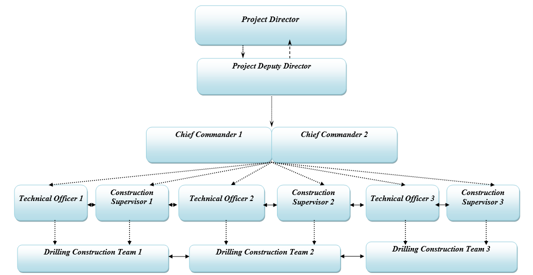
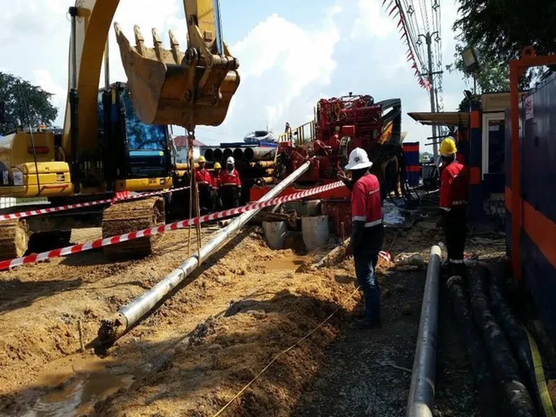
4.PERSONNEL AND EQUIPMENT
All labor and construction equipment will be mobilized to the project site in accordance with the plan for each item to meet the project schedule.
Labor:
|
No. |
Personnel |
Quantity |
|
1 |
Chief Commander |
02 |
|
2 |
Construction Supervisor |
03 |
|
3 |
Technical Officer and Occupational Safety Officer |
03 |
|
4 |
Workers, Operators |
30 |
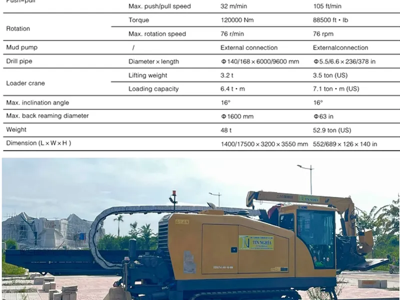
Equipment:

5 .Construction Schedule

6.Construction Methodology
6.1. Technical Solution
Based on the actual site survey and the project's requirements, the contractor proposes the construction method and suggests the casing pipe as follows:
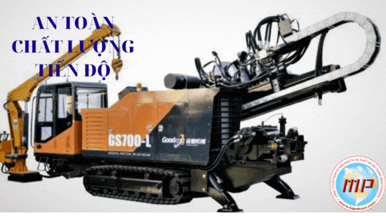
- The construction method for horizontal drilling using Horizontal Directional Drilling (HDD) technology.
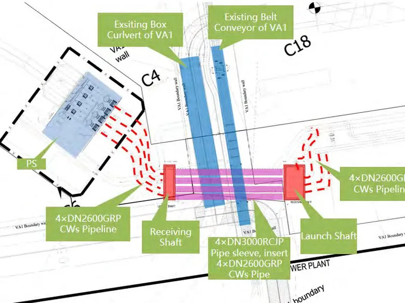
- Construction Plan: Excavation of pits on both sides of the road, using the horizontal directional drilling (HDD) technology to create the underground pipeline. This involves using a rotary cutter machine to cut and excavate the soil horizontally while simultaneously pushing a steel pipe with an internal diameter of 1100mm and a wall thickness of 10mm into the ground.

Diagram of the HDD (Horizontal Directional Drilling) Technology for Underground Drilling Construction

Figure 1. Construction Technology Diagram
Main Construction Steps:
Step 1: Excavation of Pulling Pits and Receiving Pits
Prepare the site, determine the locations for the pulling and receiving pits.
Excavate the pits, drive Larsen IV sheet piles, and install the containment frame.
Pour concrete for the bottom slab
Install the casing frame, cut the sheet piles to create the pulling/receiving hole.
Install the pulling frame and auxiliary equipment
Step 2: Install Equipment
- Lower the pulling head into the pulling pit.
- Kết nối cáp cấp điện và điều khiển
- Connect the power and control cables
- Install the cushioning block and auxiliary equipment
- Insert the pulling head into the pulling hole.
Step 3: Proceed with pipe insertion (pulling).
- Lower the pulling head and connect it to the cutting head.
- Proceed with the pipe pulling in the predetermined direction
- Lower the next pipe, weld the pipes together, and inspect and accept the welds.
- Continue with the next pipe insertion.
- Repeat the process until the cutting head reaches the receiving pit.
Step 4: Continue with pipe insertion (pulling).
- The pipeline is installed to the required length.
- Retrieve the cutting head and pulling frame
- Perform flushing and pressure testing of the pipeline as per regulations
- Dismantle the containment frame and sheet piles, restore, clean up, and return the site.

6.2. Drilling fluid used for construction projects
6.2.1. Functions of drilling fluid.
Drilling fluid is a crucial component that determines the success of the drilling process. Essentially, drilling fluid is a mixture of water, bentonite, and additives. The amount of bentonite used is calculated based on geotechnical parameters as well as the diameter and length of the borehole.
Drilling fluid has the following functions:
- Cut, break, and mix soil, rock, and sand in the tunnel where the drill bit and breaker pass through when pumped under high pressure
- Establish and maintain tunnel stability (prevent tunnel collapse).
- Lubricate the drill bit, breaker head, and drill rod, reducing heat buildup on these tools.
- Transport soil, rock, and sand from the tunnel to the outside.
- For areas with saline-affected soil or high pH levels, certain additives are included to minimize the degradation of these functions:
Main agent: Aus – Gel
Au. Agent: XAN BORE
Au. Agent: AMC – Pac - R
Another important characteristic of the drilling fluid is its ability to be recycled through the use of recycling equipment.
6.2.2. Drilling fluid supply
This project uses top-quality drilling fluid, which has been successfully applied in most drilling projects worldwide. Currently, the drilling fluid source is supplied by reputable companies around the world.
7. QUALITY ASSURANCE PROCEDURE
The contractor must establish a quality management procedure and submit it to BDA PTSC for approval before commencing the work.
The contractor must strictly adhere to the approved quality management procedures, standards, design documents, and construction plans.
The contractor is responsible for reviewing PTSC's basic design documents and technical requirements and may propose alternative design solutions if they are more optimized.
The contractor's design documents must be evaluated and approved before construction begins. The contractor is responsible for the quality of the construction design they carry out. PTSC's review, evaluation, and approval of the design do not replace or diminish the contractor's responsibility for the quality of the construction design they execute.
Construction work must be inspected and accepted before moving on to the next step.
Materials, machinery, and equipment must be inspected, accepted, and approved by PTSC before the work can proceed.
The completion records must be submitted to PTSC for approval and then handed over to PTSC.
Warranty:
The contractor shall provide a warranty for a period of 2 years from the date of handover of the project.
>>> SEE MORE: Explanatory report on construction methods for horizontal directional drilling (HDD)
CÔNG TY CP TƯ VẤN ĐẦU TƯ & THIẾT KẾ XÂY DỰNG MINH PHƯƠNG
Địa chỉ: Số 28B Mai Thị Lựu, Phường Đa Kao, Q.1, TPHCM
Hotline: 0903649782 - (028) 3514 6426
Email: nguyenthanhmp156@gmail.com
Tin tức liên quan
1073 Lượt xem
The purpose of this document is to provide the methodology for the Contractor to execute and control the HDD drilling works across roads and canals, and the pulling of 16” steel pipes inside 20” steel casing pipes, under the Project “Fuel Pipeline System for Aircraft from the Upstream Port to Long Thanh International Airport.”
2323 Lượt xem
This purpose of this document is to describe in general terms the HDD process and methodologies that will be utilized for “Approximately 94 km of 30-inch onshore pipeline from An Minh Landfall Station to O Mon Gas Distribution Center (GDC) at Can Tho Province” section this project.
1714 Lượt xem
Execution plan for horizontal directional drilling gas pipeline project. This execution plan is proposed according to the work list which is provided by EPC as well as all the HDD geological condition are considered as the normal soil, and the HDD list is as followed.
1782 Lượt xem
The purpose of this document is to propose a method for the Project Management Consultant and the Investor to review and approve for the Contractor to execute and control the drilling process for pulling a steel pipe with a diameter of D200 under the road.
6203 Lượt xem
This document has been prepared to describe the methodology by which MCD/HDDT propose undertaking the site preparation, mobilization, drilling operations, pipe installation, pre-commissioning and reinstatement operations for the installation of the 6 HDD crossings on the Block B Omon Project - Onshore Pipeline.
2338 Lượt xem
Pipe Jacking Project of Vietnam Vung Ang II power plant. Dự án thi công khoan đường ống nhà máy nhiệt điện Vung Ang II.
Xem thêm