Horizontal Directional Drilling (HDD) Method Statement
This document has been prepared to describe the methodology by which MCD/HDDT propose undertaking the site preparation, mobilization, drilling operations, pipe installation, pre-commissioning and reinstatement operations for the installation of the 6 HDD crossings on the Block B Omon Project - Onshore Pipeline.
Horizontal Directional Drilling (HDD) Method Statement
Table of Contents
- CONTRACTORS SUMMARY
- INTRODUCTION
- CONSTRUCTION RISK ASSESSMENT
- Risk Ranking of Likelihood
- Risk Ranking of Consequence Risk
- Risk Legend
- Assessment
- PROJECT GEOLOGY
- DOWN HOLE SURVEY SYSTEMS
- Downhole Survey Techniques
- Survey Overview
- Survey Systems – Magnetic Steering Tool – Description
- Survey Systems – Paratrack 2 Wire Tracking – DescriptioSurvey Systems – A.C. Solenoid System – Description
- EXECUTION
- Pilot Drilling
- Pilot Tooling
- Reaming
- REAMED HOLE SIZE
- REAMING STEPS
- REAMING RATE OF PENETRATION
- PULL BACK
- MUD PROGRAM
- Cuttings Treatment & Displacement Removal
- FRAC-OUT MANAGEMENT
- Prevention
- Frac out management
- Frac-out Contingencies
- DEMOBILISATION
- PRELIMINARY CONSTRUCTION EQUIPMENT LIST
- Rig - American Augers DD440T
- PRELIMINARY KEY PERSONNEL CHART
- DESIGN AND CONSTRUCT SCHEDULE........................................................................................................................... 18
- CONTRACTORS SUMMARY
HDD (Thailand) Co. Ltd. is an HDD specialist with expertise in delivering technically challenging multi rig HDD projects worldwide. We strive to exceed industry standards and bring exceptional quality and value to our clients. HDDT has over 150 professionals working on projects worldwide including Asia, Australasia, and Africa. HDDT have ensured success on crossings of 42” over 1,465 metres and smaller diameters over 3,014 metres Our carefully selected specialist staff provide the highest standards of quality, safety, and environmentally considerate production possible.
HDDT’s objective is to exceed industry standards and bring exceptional quality and value to our clients. HDDT has continued involvement in every major pipeline project in Thailand since 2012 and continues to deliver the best Horizontal Directional Drilling experience.
- INTRODUCTION
This document has been prepared to describe the methodology by which MCD/HDDT propose undertaking the site preparation, mobilization, drilling operations, pipe installation, pre-commissioning and reinstatement operations for the installation of the 6 HDD crossings on the Block B Omon Project - Onshore Pipeline. The 30” pipelines are to be installed with an additional 6” FOC duct as per the supplied alignment sheets.
Prior to construction a detailed engineering design will need to be prepared to further evaluate and determine the final design and methodology. The following method statement presents our proposal based on our understanding of the crossing requirements and may alter following the detailed design works.
- CONTRUSTION RISK ASSESSMENT
To provide suitable mitigation measures risks need to be properly identified, a Construction Risk Assessment has been developed to help identify constructability risk and consequences without control. The risk is measured by likelihood, consequence, and severity. Risk is then reassessed with control measures in place to determine if the risk is acceptable. Ideally our risk score after control measures should be 6 or below to be considered tolerable.
-
- Risk Ranking of Likelihood
|
Rank |
Probability |
Description |
Likelihood |
|
1 |
1% chance |
Occur only in exceptional circumstances |
Rare |
|
2 |
5% chance |
Could occur at some time |
Unlikely |
|
3 |
10% chance |
Should occur at some time |
Possible |
|
4 |
50% chance |
Probably occur in most circumstances |
Likely |
|
5 |
100% chance |
Expected to occur in most circumstances |
Almost certain |
-
- Risk ranking of Consequence
|
Rank |
Financial Impact |
Environmental Impact |
Consequence |
|
1 |
< $10,000 |
Minor localized environmental harm rectified within hours |
Insignificant |
|
2 |
$10,000 - $100,000 |
Minor transient environmental harm that requires days for recovery |
Minor |
|
3 |
$100,000 - $250,000 |
Significant environmental harm that requires weeks for recovery |
Moderate |
|
4 |
$250,000 - $1M |
Very serious long-term environmental harm or contamination |
Major |
|
5 |
> $1M |
Severe environmental harm or contamination |
Catastrophic |
-
- Level of Risk
|
LIKELIHOOD |
SEVERITY |
||||
|
1 - Insignificant |
2 - Minor |
3 - Moderate |
4 - Major |
5 - Catastrophic |
|
|
5 - Almost certain |
5 |
10 |
15 |
20 |
25 |
|
4 - Likely |
4 |
8 |
12 |
16 |
20 |
|
3 - Possible |
3 |
6 |
9 |
12 |
15 |
|
2 - Unlikely |
2 |
4 |
6 |
8 |
10 |
|
1 - Rare |
1 |
2 |
3 |
4 |
5 |
-
- Risk Legend
|
H |
VERY HIGH RISK (15-25) - Intolerable - Do not start activity |
|
H |
HIGH RISK (8-12) - Undesirable - Additional controls required to reduce risk |
|
M |
MODERATE RISK (4-6) - Tolerable – With controls implemented |
|
L |
LOW RISK (1-3) - Broadly acceptable - Manage by routine procedures |
|
# |
Risk |
Effect |
Primary Risk Assessment |
Control Measures |
Residual Risk Assessment |
||||
|
Likelihood |
Consequence |
Risk Score |
Likelihood |
Consequence |
Risk Score |
||||
|
1 |
Unsuitable site access |
- Loss of production |
3 |
3 |
9 |
|
1 |
3 |
3 |
|
2 |
Adverse weather |
|
3 |
3 |
9 |
|
1 |
3 |
3 |
|
3 |
Community impact |
- Stop production or complete shut down |
3 |
4 |
12 |
|
1 |
3 |
3 |
|
4 |
Inadequate engineering, planning |
- Twist off drill pipe - Bogged tooling - Loss of production - Stuck pipe - Increased pull loads |
4 |
4 |
16 |
- Evaluate ground conditions
|
2 |
3 |
6 |
|
5 |
Encounter unforeseen ground conditions |
- Drill spread not suited - Deflected pilot hole - Hole collapse |
4 |
3 |
12 |
|
2 |
3 |
6 |
|
|
|
|
|
|
|
|
|
|
|
|
6 |
Encounter obstruction |
- Drill string failure
|
4 |
3 |
12 |
|
2 |
3 |
6 |
|
7 |
Loss of fluid returns |
- Stuck product pipe - Reduce drilling rates
|
4 |
3 |
12 |
|
2 |
3 |
6 |
|
8 |
Tooling failure |
- Possible re-drill |
3 |
3 |
9 |
|
1 |
3 |
3 |
|
9 |
Drill string failure |
- Possible re-drill |
3 |
3 |
9 |
|
1 |
3 |
3 |
|
10 |
Increased pull load |
- Stuck pipe
|
4 |
3 |
12 |
- Well prepared launching pit |
1 |
3 |
3 |
|
|
|
- Damage to pipe or coating. |
|
|
|
- Quality pilot profile |
|
|
|
|
11 |
Coating damaged |
|
3 |
5 |
15 |
- Final ream size to be minimum 1.3 times the product diameter - Buoyancy control when required |
1 |
5 |
5 |
|
12 |
Pipe stuck |
- Possible re-drill - Abandon pipe |
3 |
5 |
15 |
|
1 |
5 |
5 |
|
13 |
Loss of connection to the product pipe |
- Pin retainers fail |
2 |
4 |
8 |
|
1 |
4 |
4 |
- ROJECT GEOLOGY
An overview of the geotechnical information is shown above, the green shaded cells indicating jetting pilot hole methodology and barrels for reaming. All suitable tooling options will be available with a suitable number of spares on- site. The final tooling plan will be prepared before mobilizing and is site specific to design, services, and final geotechnical information.
Local borehole information is indicated by a Standard Penetration Test (SPT), this is a field test that involves driving a 2” split spoon sampler into the soil by dropping a hammer of a specific weight to determine the number of blows necessary to drive the sample 12 inches. The number obtained is the standard penetration resistance value (N) and is used to estimate the relative density of cohesion less soils. The geotechnical borehole information supplied suggest predominantly soft silty sands with clay and should present a relatively straightforward approach for HDD methodology with a good mud program, jetting pilot tooling, and LTBR neutral buoyancy barrel reamers.
5. DOWN HOLE SURVEY SYSTEMS
- 1. Downhole Survey Techniques
- It is proposed to use three separate downhole surveying techniques to achieve the accuracy required for these crossings. The three methods/techniques have been selected after considering all the available surveying methods, and are as follows:
- Magnetic steering tool utilizing the Vector Magnetics P2 Magnetic Steering ToolSurface Coil Tracking utilizing the Vector Magnetics P2 system.
- Solenoid Tracking utilizing the Vector Magnetics AC Solenoid system.
- 2. Survey Overview
- The methods proposed will allow for optimum tracking of the drill bit during the drilling process, so that the position of the drill will be known always in relation to the proposed profile.
- The primary steering tool will be the Vector Magnetics Steering Tool, the secondary system will be surface tracking utilizing the Vector Magnetics Paratrack 2 wire tracking system, and the third system will be surface tracking utilizing the Vector Magnetics AC Solenoid system.
- A wire will be laid along or offset to the center line at the entry point and a closed loop will be formed by running a return line back to the start of the wire. The main problems associated with directional control through this section are expected to be magnetic interference from the drilling equipment near the entry point. This is typically only experienced over the initial 20 or 30 meters, and the use of the tracking from the wire will eliminate any error from this source. An accurate determination of the line azimuth (entry to exit reference line) is expected from this entry wire. It is proposed to have available a AC Beacon to be used once over the water or areas where the surface wire is not possible. By utilizing these tracking systems, the position of the drill will be known confidently by a minimum of 2 independent systems at any one time to a position of +/- 200 mm.
- 3. Survey Systems – Magnetic Steering Tool – Description
- The Magnetic Steering Tool is manufactured by Vector Magnetics LLC. The tool consists of a sensor package located in the bottom half of the tool, and a data processing section located in the upper half. The sensor package consists of three triaxial fluxgate AC and DC magnetometers, and three triaxial accelerometers. The triaxial configuration allows the tool to be all angle capable.
- The fluxgate magnetometers measure the parameters Bx, By, and Bz where B is the magnetic vector component along the axis of each magnetometer. The x axis is defined as the high side of the tool. The accelerometers measure Gx, Gy, and Gz where G is the measured acceleration component of the earth’s gravitational field.
- From these raw sensor readings, the direction of the tool is computed in degrees of Azimuth relative to magnetic north, as well as the inclination in degrees from vertical and tool face in degrees from high side (x axis of the tool).
- The tool is linked to the surface via a single core cable of size 4-6mm square, which enables real time data to be viewed whilst drilling, and for surveys to be taken directly on to a surface computer. The tool is placed in the drill string inside one or two non-magnetic drill collars. This will allow the tool to be placed in a relatively magnetically clean environment away from interference from the drill string and the jetting assembly. As well as recording the inclination and azimuth, the instrument also measures the total magnetic field, B total, and the angle of magnetic flux, the Dip. These two parameters are used for Q.A purposes as they indicate the presence of any external magnetic interference.
- The B total and Dip are known for any area and can be derived either from published magnetic charts, commercially available modelling software, or simply by measuring the earth’s background field in the local area. Additionally, the measured parameter, G total, is used as a Q.A indicator as it indicates that the tool was stationary while the survey was being taken.
- 4. Survey Systems – Paratrack 2 Wire Tracking – Description
- Paratrack 2 is a wire based locating system. An AC current is passed through a single core wire that either forms a closed coil of known geometry, or a single wire grounded at both ends. As the current passes along the wire, an alternating magnetic field of known strength and geometry is produced. The magnetic vector component of this field is measured by the steering tool downhole, and the software is then able to model the position of the steering tool in relation to the coil. As the generated field is of a known frequency, it is possible to filter out most the background noise, enabling a much higher signal to noise ratio, and hence more accurate tracking at greater depths.
- The Paratrack 2 system requires a local based co-ordinate system based on a reference azimuth. This is usually the line azimuth and is the line between entry point and exit point. Positions measured by the Paratrack 2 system are defined by the distance along this line, (Away), the distance to the right of the line, (Right), and the elevation. Each corner of each coil needs to be pegged. These pegs will be placed to provide the maximum accuracy achievable. Corners will be set so that the wire can be placed between the corners in a straight line both in the horizontal and vertical planes. If this is not possible then an extra corner will be added.
- Generally, the wire will be placed so that it will be positioned above the steering tool downhole, i.e. on center line. As the accuracy of the system relies on the accurate positioning of the coil itself then it is important that the coil corners are defined as accurately as possible. The corners will be pegged out, and then picked up by a land surveyor. The grid co- ordinates as supplied by the land surveyor can then be translated into the Away, Right, and Elevation co-ordinate system for entry into the Vector software.
5. Survey Systems – A.C. Solenoid System – Description
The AC Beacon consists of two wire wound coil solenoids mounted bi-axially on a non-magnetic table. Power to the AC Beacon is supplied via a 12 V DC deep discharge battery. Typically, the Beacon is oriented with a Total Station to a known azimuth, either the line or actual drill azimuth, and is placed either on or offset to the drill path. The Beacon can then be remotely actuated via the Paratrack software. Once the Beacon has been energized, it generates a known AC magnetic field. As the Beacon is in effect a point source, the generated field can be modeled accurately, allowing for an accurate determination of the steering tool position. Depending on the signal to noise ratio, it is possible to track up to 125m away from the Beacon, allowing in effect for a 250m tracking window.
The AC solenoid will work on the same local based co-ordinate system (away, right, elevation) that is used both for the Steering Tool and the Paratrack 2 system. The solenoid can be placed anywhere that is convenient along the drill path.
- EXECUTION
- Pilot Drilling
Successful drilling projects require the use of quality down hole tooling, drill pipe, connections, and tooling management. The following overview of tooling proposed for this project is as follows, however can change with ground conditions. A 9 7/8” tri-cone bit and jetting assembly is planned for soft crossings and a down-hole mud motor will be used if conditions require for firmer ground conditions.
The pilot drill string will be advanced along the engineered and approved path from the entry surface location to the exit location, as the string is advanced the action of the bentonite being pumped down the string and through the bit erodes the soil formation in the soft formations. For harder formations, as the drill fluid is pumped through the drill string it flows through the mud motor and rock bit and uses mechanical action to cut or chip away the hard and rock formations before it exits through nozzles in the bit and flows back to surface through the annulus between the drill pipes and the borehole walls. The drill fluid then carries these cuttings out of the hole.
The bit is steered by means of an offset behind the bit, the string is rotated to drill straight and the offset positioned to achieve build or steer depending on the design profile and the ongoing survey data. Pilot-hole data will be recorded for as-built drawings and at the completion of the pilot-hole drilling as-built information will be prepared including, tabulation sheets of co-ordinates, length, depth, inclination, azimuth and drawing, which accurately describe the location of the pilot hole, will be submitted.
The anticipated rate of penetration (ROP) suggests that the pilot drilling bit will not need to be changed during the drilling of each pilot hole.
-
- Pilot Tooling
Premium drill pipe will be used for this project built to API RP7G and API 5D specifications. Based on the information available the BHA will entail a 6 ½” non-magnetic drill collar, orienting sub, offset or bent sub, 9 7/8” tri-cone bit, and 6 5/8” drill pipe employed on the longer crossings and more flexible 5” drillpipe for the shorter crossings.
Based on the the geotechnical information supplied, we expect soft ground jet tool pilot however, if hard ground is encountered the jetting assembly will not be suitable therefore a 6 ¾” BICO mud motor will be available. This will be coupled with a 9 7/8” tri-cone bit and 6 ½” NMDC.
Motor Specifications 6-3/4" P100 XL Flex Drill
|
Operating Data |
||
|
Flow Range |
1,135 - 2,270 lpm |
300 - 600 gpm |
|
Motor Pressure |
47 bar |
675 psi |
|
Bit Speed |
60 - 145 rpm |
|
|
Torque |
9,080 Nm |
6,700 ft-lbs |
|
Power |
HP (Kw) |
185 (138) |
|
Physical Data |
||
|
Power Section Configuration |
Stages |
5 |
|
Lobes |
7/8 |
|
|
Bit to Stabilizer |
648 mm |
25.5 in |
|
Bit to Bend |
2,160 mm |
85.1 in |
|
Overall Motor Length |
7.9 m |
26.0 ft |
|
Weight |
1,035 kg |
2,285 lbs |
|
Connections |
Box |
4-1/2" REG, Top and Bottom |
|
Bit Size |
200.0 - 250.8 mm |
7-7/8 to 9-7/8 in |
Based on the information on the regional geology, the jetting assembly will be available for soft sections and if required, a standby motor will be on-hand.
-
- Reaming
On successful completion of the pilot hole, reaming tools of various sizes will be progressively added at pipe side and drawn back through the hole to enlarge the hole over its full length. Typically, reamers will be sized to manage the amount of additional material cut with each reaming pass such that it is reasonably consistent. The drilled hole will be progressively enlarged until its diameter is approximately 30 to 50 % larger than the product pipe, depending on soil conditions. Combinations of tools such as fly cutters, barrel reamers and hole openers may be used during reaming operations as conditions require.
There are many different reamers of varying design and quality available to the HDD market today however generally speaking there are 4 main styles of reamers used in most HDD applications.
Fly-cutters
Fly-cutters are used in softer ground conditions and have their place in stiff clay with compacted sand applications, these tools need to be stabilised front and rear to ensure the tool is centralised and to help with the conditioning of the borehole. They are quite aggressive and designed to tear away at the formation and should always be followed with a barrel reamer to stabilise the borehole.
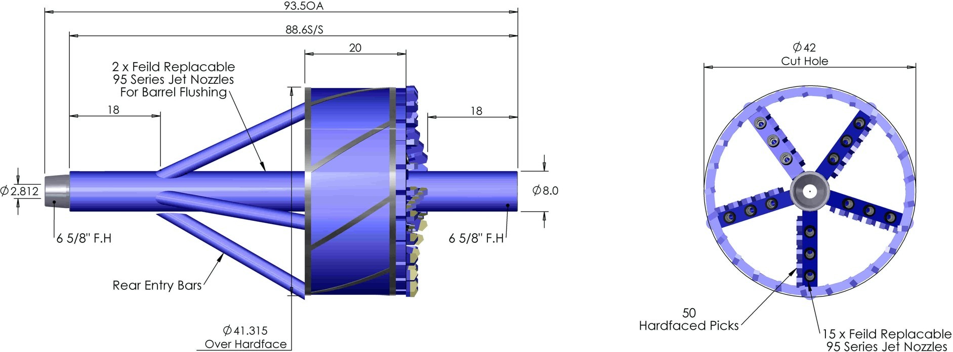
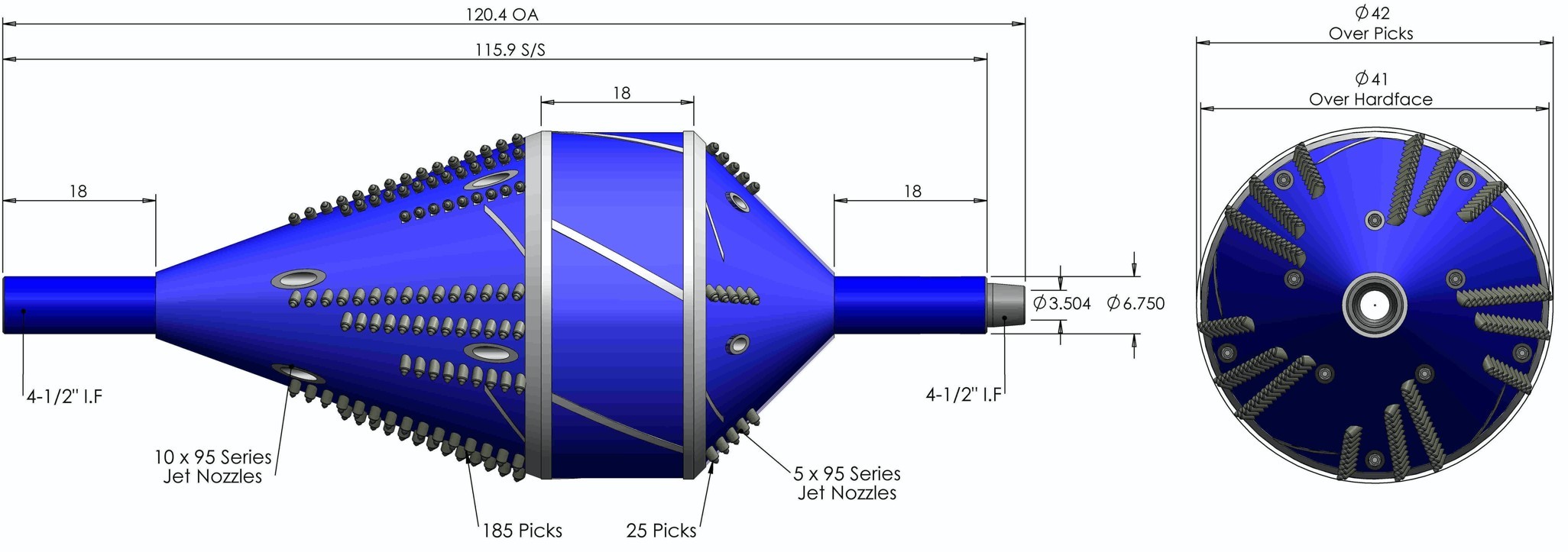
Barrel reamers are a great option in soft to medium clayey silts and sands, they are specially designed to be self- centralising and self-conditioning. The LTBR style barrels are built with chambers to lessen the down hole weight of the tool and therefore cut straight and evenly. They are mostly used in soft ground as a hydraulic cut but are armed with enough teeth that if harder sections are encountered the mechanical cut can take over.
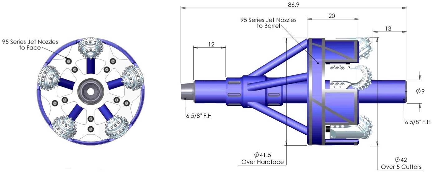
Mixed ground backstay style hole openers are specially designed to cut through softer material with rock sections, the body is designed to allow enough flow through for clays and sand without packing off the cutters. The cutters are interchangeable so that soft rock or hard rock cutters can be changed to suit the expected conditions.
Transco mixed ground backstay type hole opener
Conclusion
For the ground conditions on this project both fly cutter style and LTBR barrel reamers will be employed to cover the range of soft ground expected.
-
- REAMED HOLE SIZE
There are a great many factors to consider on appropriate ream sizes that should be considered for the hole opening of any HDD project. A general industry standard is 1.5 times the diameter of the product pipe being installed however this is generally aimed at the smaller rigs and pipe diameters. Examples of variations to this rule can include;
Hard rock
Hard competent rock is challenging to drill however the borehole once drilled is very stable and unlikely to change, there is no swelling, danger of collapse, and if properly cleaned and conditioned requires very little pull force. As such the reamed diameter can be much closer to the diameter of the product pipe therefore 1.2 times the diameter in shorter crossings to 1.3 time the diameter in longer installations is acceptable.
Clay
Reactive clays swell with the introduction of liquid (including standard drill fluids) and as such the 1.4 times the pipe diameter rule is often strongly recommended. Any delays (such as breakdowns or tie-ins) during pullback in reactive clays can be detrimental to the installation as the clay swells around the partially installed pipeline.
Unstable strata
Unstable materials such as loose sand, gravel, cobble or boulders are generally not suitable for HDD methodology however given suitable control measures are implemented or the section is short the hole size could be very important. The type of ground should be carefully considered during pilot hole and primary reaming passes to determine the safest final ream size.
Length of crossings
Shorter crossings can be installed into holes closer to the size of the pipe to mitigate the risk of subsidence and ground heave however longer crossings may require a larger reamed diameter especially in distances over 2,000 metres. These designs should be considered site specific and no hard and fast rule is applicable.
As-built pilot profile
The geometry is also a determining factor in the final ream size, this is due to the geometry and any deviations encountered during the pilot bore phase and should be considered after the completion of the pilot bore.
-
- REAMING STEPS
Reaming steps are also geotechnical and site specific, for this project we have chosen a preliminary staged program of between 0.2m3 per metre cut and 0.4m3 per metre cut, this is a conservative figure and may be modified to suit the actual encountered conditions.
|
Step |
Type |
Diameter |
Cut Volume (m3/m) |
|
Pilot hole |
Jet or motor |
9 7/8” |
0.02 m3/m |
|
Ream 1 |
Barrel |
12” |
0.22 m3/m |
|
Ream 2 |
Barrel |
24” |
0.29 m3/m |
|
Ream 3 |
Barrel |
34” |
0.37 m3/m |
|
Ream 4 |
Barrel |
42” |
0.30 m3/m |
|
Conditioning pass |
Barrel |
34” |
- |
|
Pullback |
Swivel / barrel |
34” |
- |
-
- REAMING RATE OF PENETRATION
The Rate of Penetration (ROP) must be balanced against the quality, flow rate, carrying capacity and bottom up time of the drill fluid. Several factors can determine the optimum ROP for reaming and it is very important that proper hole cleaning is maintained during this operation. To maintain borehole stability the return fluid should contain no more than 25% cuttings with 15% ideal and 20% absolute planned maximum.
|
Reaming Step |
Pump rate (ltr/min) |
Annular velocity (m/min) |
Desired Cuttings % |
Maximum ream speed (min/joint) |
|
12” Ream |
800 |
13.27 |
15% |
1.86 |
|
24” Ream |
1,500 |
5.38 |
15% |
9.23 |
|
34” Ream |
1,800 |
3.14 |
15% |
10.32 |
|
42” Ream |
2,000 |
2.27 |
15% |
9.74 |
The maximum rate of penetration in minutes per joint is determined by the pump rate multiplied by the desired maximum cuttings percentage in the return drill fluid divided by the cut volume. Minimum optimal reaming annular velocity is around 2 metres per minute. The chart shows the maximum ream speeds using 5” drill pipe.
- PULL BACK
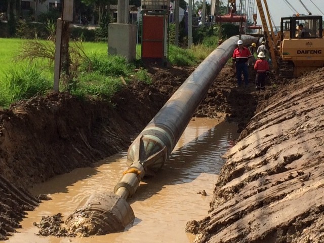
Barrel Reaming Schematic
- MUD PROGRAM
A good quality freshwater mud program is expected to be suitable for these crossings. Fresh water will be delivered to site from a local approved water source. All drilling fluid used for the project will consist of water (more than 95%) plus natural clay, also referred to as bentonite. Small quantities of additives may be used to improve the properties of the mud to suit the ground conditions encountered.
The mud serves several purposes, including the stabilization of the bore-hole walls, lubrication and cooling of down hole tools and the suspension and transport of the cuttings produced during drilling operations. When the mud is at the correct parameters for the prevailing drilling conditions it will be pumped from the tank and then via the mud pump to the drill string. The mud will return to surface via the annulus carrying the cuttings with it and in order to reduce the total volume used, the mud will be cleaned and recycled with the separation system on site and spoil removed from site to an approved disposal area.
All materials used in the mud, including the bentonite are environmentally harmless. Suppliers will be requested to provide MSDS to confirm this and copies of these MSDS sheets will also be present on each site.
-
- Cuttings Treatment & Displacement Removal
During the drilling process cuttings are produced by the reaming process, these will be stored in the disposal pit on-site and taken by dump truck to an approved dumpsite on completion of the drilling activities. During pull back the drill fluid will be displaced and stored in the disposal pit to be removed with the cuttings.
- FRAC-OUT MANAGEMENT
During drilling in very soft or fractured formations inadvertent fluid returns can be encountered at the surface, this is termed a ‘frac-out”. Frac-outs occur when the annular pressure exceeds the hydrostatic head required to reach the surface either through very soft formation or via natural or manmade faults in the ground.
-
- Prevention
To reduce the chances of a frac-out occurring, the quality of mud will be monitored by frequent inspection of the mud returns. The solids generated by the reaming process are estimated by using the fluid weight (drill fines contained in the fluid), this in turn, can be used to calculate the minimum minutes needed to drill each joint to ensure the fluid is not over loaded with cuttings causing undue down hole pressure.
Mud tests will be regularly carried out and recorded to ensure and monitor the quality of the drilling fluid, mud weight, viscosity, sand content and a log of water, bentonite, and additives.
The drill profiles will be designed considering the geotechnical and topographical information available to best suit the conditions and reduce the risk of frac-outs.
-
- Frac out management
Early detection of imminent frac-outs can be identified in three ways, returns, mud pressure or gradual loss of fluid levels in the storage tanks. The driller will monitor and record the mud pressure for each joint, drill fluid returns or lack thereof is also monitored at both entry and exit pits and are coordinated by the driller and drill supervisor.
Throughout the drilling operations, the drillers, foreman and HDD crew will be in constant communication via radios to act on and minimize the event of frac-outs without delay.
For bentonite spills on land, sandbags, pumping equipment, materials and plant will be stored where they can be easily and quickly brought to the breakout point. The crew monitoring the site will be equipped with radios for instant communication with drill operator.
-
- Frac-out Contingencies
The use of advanced formula drilling fluids will help to minimize the risk of frac-out. These blended products form an impermeable filter cake around the drill annulus due to the alignment of the clay platelets. However, if drilling mud continues to break out at the surface in addition to the contingency action above a loss circulation material (LCM) will be prepared and pumped into the system to stem the flow. In extreme cases and where the ground conditions are favorable it may be necessary to ‘trip out’ and recommence drilling at a different elevation.
- DEMOBILISATION
On satisfactory completion of the installation the drilling rig and ancillary equipment will be dismantled and loaded out for demobilization to base. All temporary excavations will then be either backfilled or securely fenced for shorter periods if they are to be left open for tie-in activities, any open pit or excavations must comply with the Safety, Health & Environment (SHE) Plan. All surplus materials and waste will be removed from the work areas.
- PRELIMINARY CONSTRUCTION EQUIPMENT LIST
|
Crossing |
Length |
Rig |
Calculated Pull force |
|
Xeo ro Canal Crossing |
360 m |
DD440 |
43 tons |
|
Cai Lon River |
980 m |
DD440 |
107 tons |
|
Cai Be River |
486 m |
DD440 |
55 tons |
|
National Road No 61 |
270 m |
DD440 |
33 tons |
|
Thot Not Canal |
372 m |
DD440 |
43 tons |
|
National Road No 91 |
230 m |
DD440 |
31 tons |
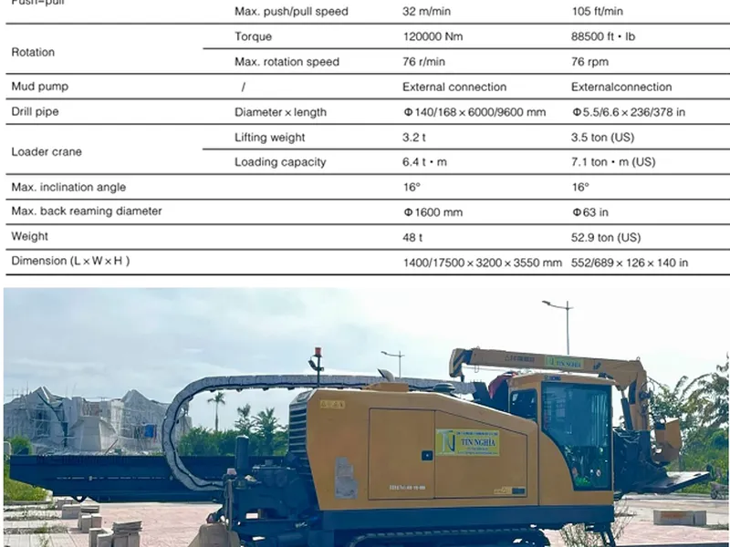
Proposed rig for this project is an American Augers DD440T (200 ton). This rig is well within the capacity to complete any of the crossings currently planned.
-
- Rig - American Augers DD440T
|
POWER TRAIN |
|
|
Engine |
Cummins |
|
Rating |
600 HP (447 kW) |
|
Fuel Capacity |
160 U.S. Gallons (605 L) |
|
Hydraulic Capacity |
200 U.S. Gallons (757 L) |
|
CARRIAGE CAPACITIES |
|
|
Maximum Thrust/Pullback |
440,000 lbs. (200 Tonnes) |
|
Carriage System |
2 motor rack and pinion drive |
|
Maximum Carriage Speed |
(29 m)/minute |
|
Carriage Motors |
2 Hydraulic 160cc, Radial Piston |
|
Carriage Gearbox |
2 Planetary Drives |
|
ROTARY CAPACITIES |
|
|
Rotary System |
3 Pinion & Gear Drive |
|
Maximum Rotary Torque |
43,90 ft-lbs. (59,590 Nm) @ 37 RPM |
|
Maximum Rotary Speed |
150 RPM |
|
Rotary Motors |
(2) Hydraulic, 486cc, Axial Piston |
|
BREAKOUT UNIT |
|
|
Wrench Style |
Triple Jaw 10 3/4 in (273 mm) Separation |
|
Maximum Breakout Torque |
60,000 ft-lbs. (81,350 Nm) |
|
Clamp/Grip Range |
2 3/4 in. – 10 3/4 in. (70 – 273 mm) OD |
|
DRILL RIG |
|
|
Drill Angle |
10° - 18° |
|
Drill Pipe |
Range II 4-1/2 in and 6 5/8 in API pipe |
|
Travel System |
Self Propelled Steel Track Crawler Assembly Maximum Travel Speed: 1.4 mph (2.25 kph) |
|
DIMENSIONS |
|
|
Length |
50 ft. 9in. (15.47 m) |
|
Width |
|
8 ft. 2 in. (2.51 m) |
|
|
Height |
11 ft. 10 in. (3.61 m) |
||
|
Weight |
90,260 lbs. (40,941 kg) |
||
|
# |
Crossing |
Pipe |
Length |
Rig |
Days |
|
1 |
Xeo ro Canal Crossing |
FOC, 30” |
360 m |
DD440 |
30 |
|
2 |
Cai Lon River |
FOC, 30” |
980 m |
DD440 |
49 |
|
3 |
Cai Be River |
FOC, 30” |
486 m |
DD440 |
37 |
|
4 |
National Road No 61 |
FOC, 30” |
270 m |
DD440 |
30 |
|
5 |
Thot Not Canal |
FOC, 30” |
372 m |
DD440 |
32 |
|
6 |
National Road No 91 |
FOC, 30” |
230 m |
DD440 |
29 |
|
|
Total drilling days |
207 |
|||
At rig side, the rig anchor will consist of a steel piled wall with an I‐beam spreader to the rig dead man, the position of which will be surveyed and pegged to ensure correct position in relation to any services and entry position. The piles will be driven with a vibrating piling hammer, ensuring all services have been identified, located, and exposed prior to commencing work. This will be done at the time of the civil works and before the mobilization of the drilling spread.
CÔNG TY CP TƯ VẤN ĐẦU TƯ & THIẾT KẾ XÂY DỰNG MINH PHƯƠNG
Địa chỉ: Số 28B Mai Thị Lựu, Phường Đa Kao, Q.1, TPHCM
Hotline: 0903649782 - (028) 3514 6426
Email: nguyenthanhmp156@gmail.com

Xem thêm