Construction method for HDD drilling across roads and canals
The purpose of this document is to provide the methodology for the Contractor to execute and control the HDD drilling works across roads and canals, and the pulling of 16” steel pipes inside 20” steel casing pipes, under the Project “Fuel Pipeline System for Aircraft from the Upstream Port to Long Thanh International Airport.”
TABLE OF CONTENTS
1.2 PURPOSE OF THE DOCUMENT.. 4
1.4 DEFINITIONS AND ABBREVIATIONS. 5
3.0 Construction Equipment.. 10
4.0 Temporary Works for Construction.. 10
5.0 Drilling Construction Schedule.. 11
6.0 Construction Materials. 11
7.0 Depth and Clearance to Underground Structures. 11
8.0 Construction Method Statement.. 12
8.1 Construction Sequence.. 12
8.2 Application for Construction Permit.. 13
8.3 Construction Method for Pipeline Trench Excavation.. 14
8.4 Horizontal Directional Drilling (HDD) Construction Method.. 15
8.5 Site Cleaning and Reinstatement.. 24
9.3 Environmental Sanitation.. 26
9.4 Fire and Explosion Prevention, Internal Traffic Safety.. 26
1.0.GENERAL INTRODUCTION
1.1.PROJECT OVERVIEW
ABC……..Joint Stock Company plans to invest in the installation of a fuel pipeline and technological system with the following project scale:
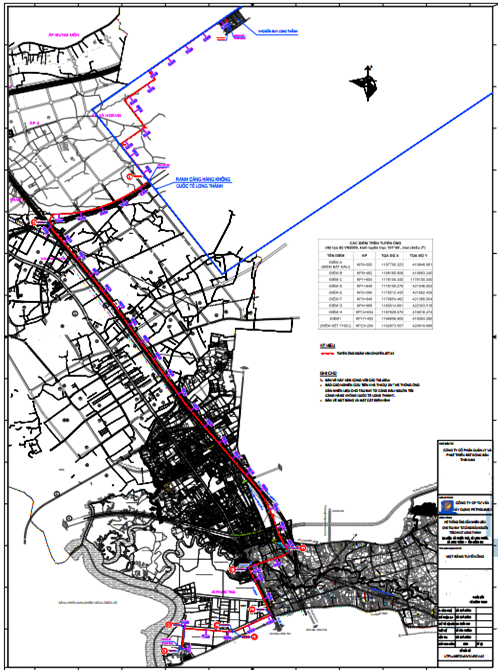
Figure: Fuel Receiving Pipeline Diagram
1.2.PURPOSE OF THE DOCUMENT
The purpose of this document is to provide the methodology for the Contractor to execute and control the HDD drilling works across roads and canals, and the pulling of 16” steel pipes inside 20” steel casing pipes, under the Project “Fuel Pipeline System for Aircraft from the Upstream Port to Long Thanh International Airport.”
1.3.LEGAL DOCUMENTS
- Law on Construction No. 50/2014/QH13 dated June 18, 2014 of the National Assembly of the Socialist Republic of Vietnam, 13th Legislature, 7th Session;
- Law on Environmental Protection No. 72/2020/QH13 passed on November 17, 2020, effective from January 01, 2022, of the 14th Legislature, 10th Session of the National Assembly;
- Decree No. 13/2011/ND-CP dated February 11, 2011 of the Government on safety of onshore petroleum works;
- Decree No. 25/2019/ND-CP amending and supplementing a number of articles of Decree No. 13/2011/ND-CP dated February 11, 2011 of the Government on safety of onshore petroleum works;
- Decree No. 46/2015/ND-CP dated May 12, 2015 of the Government on quality management and maintenance of construction works;
- Decree No. 68/2019/ND-CP dated August 14, 2019 of the Government on management of construction investment costs;
- Decree No. 15/2021/ND-CP dated March 03, 2021 of the Government detailing a number of contents on management of construction investment projects;
- Decree No. 10/2021/ND-CP dated February 09, 2021 of the Government on management of construction investment costs;
- Circular No. 07/2016/TT-BXD dated March 10, 2016 of the Ministry of Construction guiding the adjustment of construction contract prices;
- Circular No. 08/2016/TT-BXD dated March 10, 2016 of the Ministry of Construction guiding a number of contents on consultancy contracts;
- Circular No. 09/2019/TT-BXD dated December 26, 2019 of the Ministry of Construction guiding the determination and management of construction investment costs;
- Circular No. 16/2019/TT-BXD dated December 26, 2019 of the Ministry of Construction guiding the determination of project management and construction investment consultancy costs;
- Circular No. 18/2010/TT-BXD dated October 15, 2010 of the Ministry of Construction regulating the application of standards and technical regulations in construction activities;
- Circular No. 06/2021/TT-BXD dated June 30, 2021 of the Ministry of Construction regulating the classification of construction works and guiding the application in construction investment management.
1.4.DEFINITIONS AND ABBREVIATIONS
Investor (Project Owner): AB……………. Joint Stock Company
Project: Fuel Pipeline System for Aircraft from the Upstream Port to Long Thanh International Airport
BDA : Project Management Board (PMB) / Project Board
CBAT : Safety Officer (SO)
CBKT : Technical Officer (TO) / Technical Engineer
MMTB Machinery and Equipment (M&E)
HT System (Sys.)
2.0.CONSTRUCTION MANPOWER
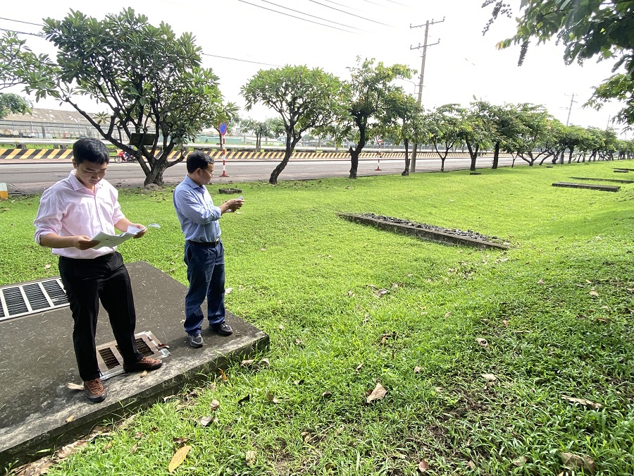
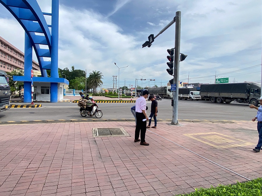
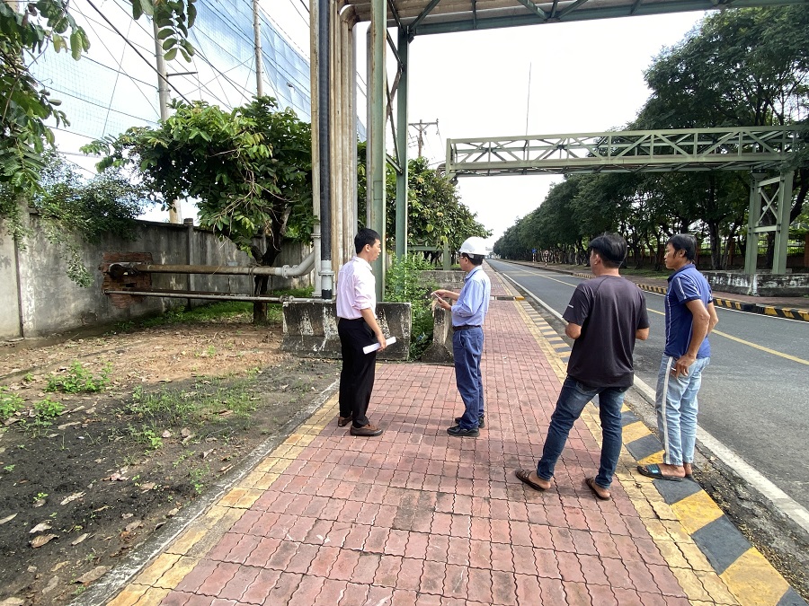
Survey the actual project to develop underground drilling construction measures
List of Personnel Participating in HDD Construction:
According to the construction organizational chart of the project as follows:
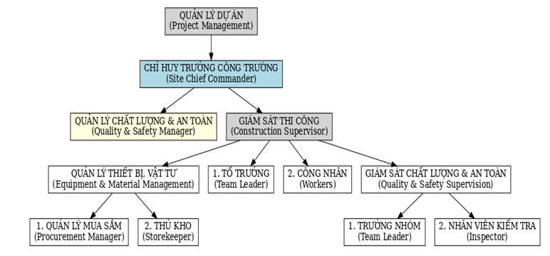
Responsibilities
1. Project Manager
The Project Manager is responsible for applying this procedure and ensuring that all safety measures are strictly followed.
2. Site Manager (Chief of Construction)
The Site Manager is responsible for the overall management of all construction activities at the site.
Ensures that designated personnel fully comply with this procedure.
3. Quality Assurance/Quality Control (QA/QC) and Safety
QA/QC Manager: Ensures that all activities comply with the approved design documents, technical instructions, and applicable standards. Responsible for QA/QC technical guidelines and documentation.
Safety Manager: Responsible for all HSSE (Health, Safety, Security, and Environment) activities at the site.
Safety Supervisor:
Ensures safe execution of works.
Conducts Tool Box meetings at the beginning of shifts and HSSE meetings prior to work commencement.
Maintains proper communication channels in case of emergency.
Ensures that workers follow safe work methods, identify hazards, and comply with work procedures.
Ensures that all construction activities are carried out in accordance with relevant safety regulations.
4. Construction Supervisor
Supervises construction works in strict compliance with the approved method statements and project specifications.
Ensures that all required work permits are prepared prior to commencement.
Enforces compliance with project safety procedures.
5. Team Leader / Foreman
Provided with full personal protective equipment (PPE).
Supervises the assigned work tasks.
Complies with general project regulations.
Ensures workplace cleanliness after completion of work.
Receives consultation on risk assessment organization and designates personnel for assigned tasks.
Participates in risk assessment activities.
Immediately reports identified hazards to the Supervisor or Employer and continues work only upon their approval.
Reports any workplace changes.
Informed about risks to safety and health and the necessary measures to eliminate or minimize them.
Participates in decision-making on preventive and protective measures.
Requests the Employer to implement appropriate measures and submits proposals to reduce or eliminate hazards.
Cooperates with the Employer to maintain a safe working environment.
Receives training/instructions on safety measures.
Takes utmost care for the safety and health of workers affected by their actions, in accordance with training and instructions provided.
6. Workers
Comply with project regulations, procedures, and method statements.
Adhere to supervision and management of construction activities.
Follow all safety measures and maintain workplace hygiene.
Immediately notify the Construction Supervisor or responsible persons of any risks or incidents at the site.
Handle risks and incidents in accordance with method statements, safety procedures, and supervisory instructions.
7. Materials and Equipment/Warehouse Manager
Complies with the project’s materials management procedures.
Responsible for receiving, securing, and managing materials to prevent loss.
Controls movement of materials in/out of the site in line with project requirements.
Ensures safety of personnel, equipment, and materials.
Materials and accessories must remain dry, free from damage during transportation, lifting, and storage.
Protects materials against adverse environmental impacts (rain, humidity, mud, salt, seawater).
Stores materials in dry, ventilated areas, preferably in original packaging.
8. Procurement Manager
Develops an effective procurement plan aligned with overall project objectives.
Manages logistics, protection, and preservation of goods, warehouses, and transport means.
Coordinates closely with the warehouse department to ensure timely delivery of materials and equipment to the project.
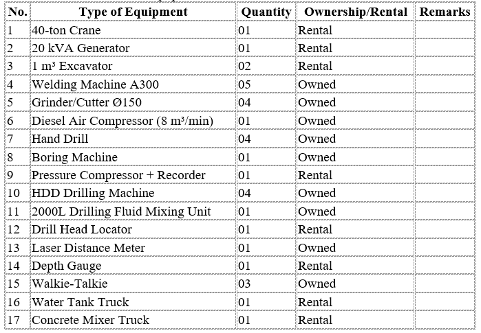
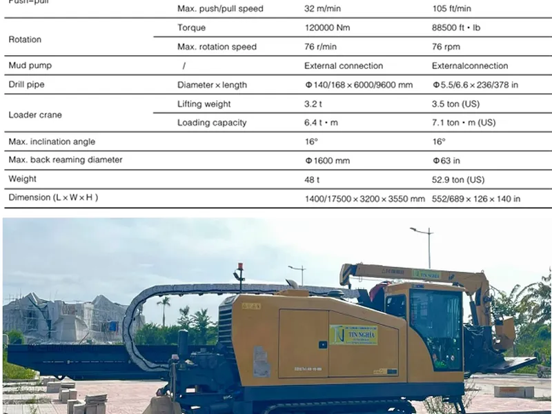
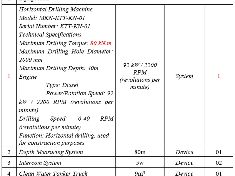
3.0.Construction Equipment
List of construction equipment:
4.0.Temporary Works for Construction
Minh Phương will transport one (01) 10-ft container containing construction equipment, tools, and other facilities, which will be placed at the laydown area within the construction site.
Site Office: located at Đồng Nai office.
Accommodation: housing for staff/workers will be rented from local households within approximately 6 km of the construction site.
Power Supply: a 20 kVA generator will be used to provide electricity for welding casing pipes and gas pipelines.
Water Supply: water for drilling operations will be provided by water tank trucks and mobile water tanks.
5.0.Drilling Construction Schedule
- Estimated construction progress is 150 days from the date of handover of construction certificate.
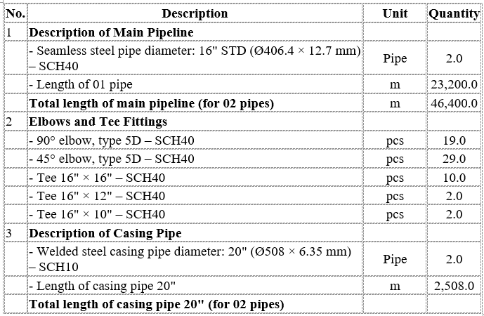
6.0.Construction Materials
List of main construction materials:
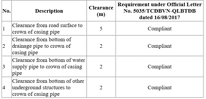
7.0.Depth and Clearance to Underground Structures
The burial depth of the pipeline when crossing roads and canals is determined based on API RP 1102 standards. Input parameters include pipe wall thickness, pipeline burial depth at the crossing, road parameters, and vehicle loadings. Stress in the pipe is verified against allowable stress, and weld fatigue is checked against fatigue limits to ensure that the pipeline is not damaged or destroyed during operation.
The burial depth of the pipeline is also determined in compliance with Vietnamese Standards: “The minimum distance from the highest point of the outer protective casing (for oil, gas, fuel, and petrochemical pipelines) to the road surface must be 5 m”, according to the approved design.
Clearance from Pipe Crown to Underground Structures at Road and Canal Crossings:
8.0.Construction Method Statement
8.1.Construction Sequence
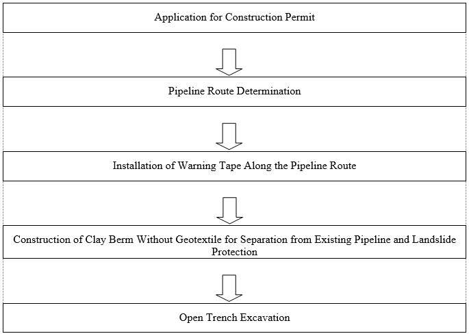
8.2.Application for Construction Permit
The Contractor shall coordinate with the Employer to obtain approvals from competent authorities and relevant agencies prior to the commencement of construction works.
The application for work permits shall be carried out in accordance with the Work Permit Procedure approved by the Employer before the execution of any works.
8.3.Construction Method for Pipeline Trench Excavation
1. Identification of Pipeline Centerline
The actual pipeline centerline will be verified using a specialized detector and confirmed by manual excavation down to the depth of the warning tape. If the warning tape is not found, excavation will continue until reaching the crown of the pipe.
Excavation pits shall be made every 100 m along straight sections, and one pit shall be made at each pipe bend. Pit dimensions are (2 × 2) m, with depth reaching the crown elevation of the existing pipeline.
The centerline of existing pipelines and fiber optic cables will be marked in the field using wooden stakes (or bamboo poles with flags, manually driven). Spacing between stakes shall be approximately 20 m for straight sections and 10 m for bends. Spacing at river crossings will be determined based on actual conditions.
Verification procedure:
Locate existing pipeline centerline using a specialized detector combined with pipe probing. For river crossings, divers may be used.
Mark excavation pit dimensions.
Place warning tapes/ropes around excavation areas.
Manually excavate down to the crown of the 3 existing pipelines.
Determine coordinates and elevation using surveying equipment (RTK).
Install stakes to mark the nearest pipeline position to the trench; backfill pits manually.
Complete all works during daytime; night works are not allowed. If excavation pits cannot be completed within the same day, warning ropes and lights must be installed around pits until work resumes.
2. Installation of Warning Tape Along Pipeline Route
After pipeline verification and centerline marking, warning tapes will be installed to define the safety boundary of the pipeline and existing underground utilities.
3. Construction of Soil Berms for Landslide Prevention and Pipeline Separation
To establish a safe corridor for trench excavation, the Contractor shall construct continuous soil berms (with or without geotextile) along the pipeline alignment.
The berms serve as separation barriers to protect existing pipelines and to prevent soil collapse during construction.
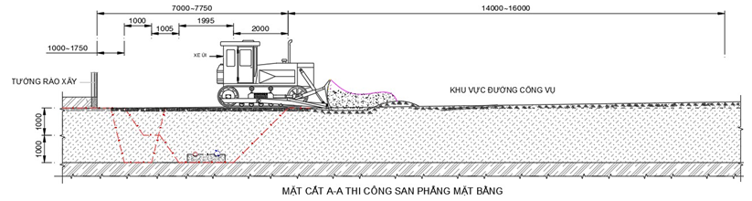
Site Grading and Leveling
Construction of Anti-Sliding Pits
8.4.Horizontal Directional Drilling (HDD) Construction Method
1. Site Survey and Construction Layout
The construction team and survey team shall review and evaluate actual soil conditions and identify potential obstacles (such as overhead lines, underground cables, drainage pipes, etc.). The exact positions for HDD rig setup, 20” pipe string welding area, pipe pullback layout, and equipment/material staging area will be determined.
Potential obstacles and solutions for accelerating progress will also be proposed if necessary.
The main difficulties are expected to arise from natural conditions: site layout, geographical location, and weather. To overcome these challenges and ensure timely progress, the Contractor shall adopt the following criteria:
Mobilize optimal resources for all work stages.
Allocate resources reasonably to ensure smooth coordination between construction teams, local authorities, regulatory agencies, and the Employer, avoiding downtime during construction.
Strictly control potential risks, identify them early, and take immediate corrective actions to prevent incidents.
2. Mobilization of Equipment and Manpower
Based on survey data, Minh Phương has selected appropriate equipment and materials for mobilization to the site. Proper selection and sufficiency of resources will ensure effective construction, adherence to schedule, and cost minimization.
Construction personnel engaged in the project must be trained in safety and hold professional certifications appropriate to their responsibilities.
3. Drilling Preparations
Use total station surveying equipment to establish the construction boundaries and alignment on site.
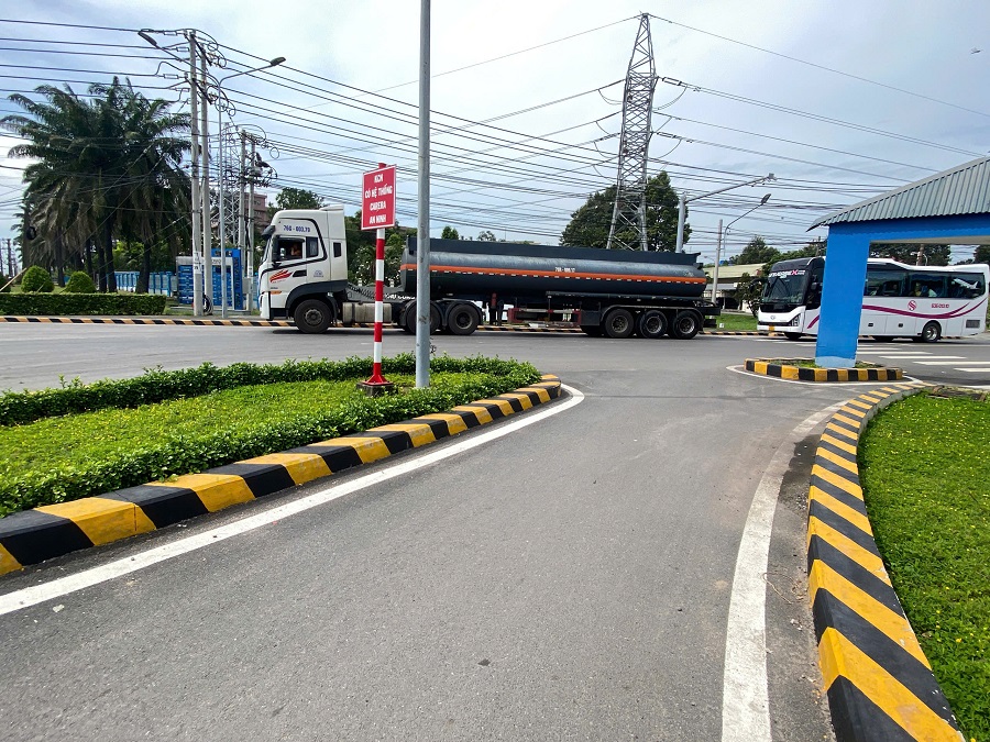
Since the project involves drilling across internal roads within the industrial park where heavy traffic exists, protective fencing and safety signage must be installed around both entry and exit pits.
Safety signs and barriers must be provided for both daytime and nighttime operations.
Normal traffic flow on main roads shall be maintained throughout construction.
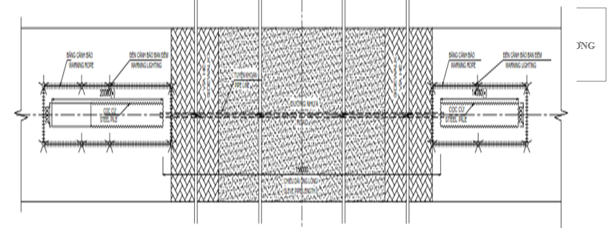
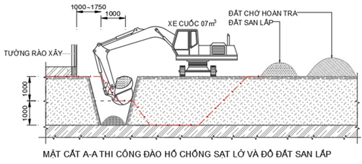
Safety Barriers and Construction Signage
Drilling Pit
To install the pipeline at a depth of 2.0 m below the road surface, the minimum drilling pit depth must be 2.5 m.
The pit provides sufficient working space for the drilling rig, drill tower, and pipe jacking operations.
Excavation dimensions: Length = 3.0 m; Width = 3.0 m; Depth = 2.5 m.
The drilling rig will be positioned at +2.0 m relative to the pit bottom elevation.
The pit will be reinforced with reinforced concrete box culvert (3 × 3 m) to prevent collapse throughout construction.
Location of the drilling pit: 32 m away from the boundary of the road traffic safety corridor.
Receiving Pit
Excavated to a depth of 3.0 m from the sidewalk elevation (0.8 m deeper than the pipeline burial depth).
Purpose: to open the borehole, receive the pipe, and facilitate pipe pulling operations for alignment.
Excavation dimensions: Length = 3.0 m; Width = 3.0 m; Depth = 2.5 m.
The receiving pit will be reinforced with reinforced concrete box culvert (3 × 3 m) to prevent collapse during construction.
Location of the receiving pit: 50 m away from the boundary of the road traffic safety corridor.
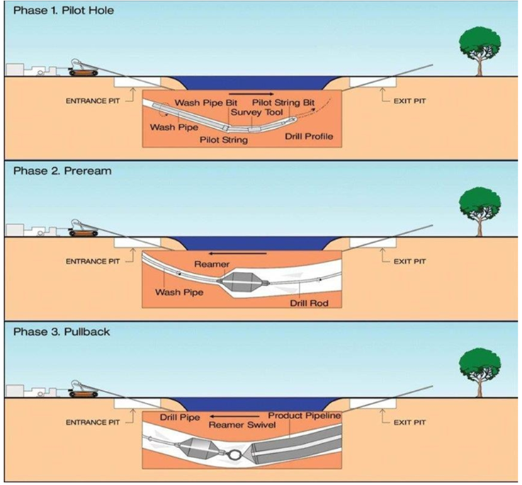
4. Pilot Hole Drilling
Based on the design drawings, a TriHawk drill bit will be used to drill at an appropriate entry angle. When the drill head reaches the designed turning point, the drill head inclination will be adjusted to the “12 o’clock” position and thrust applied, allowing the drill head to gradually change direction until reaching the horizontal alignment at the designed depth.
Drilling will then continue horizontally using the rotation–push technique until reaching the designed exit turning point. At this stage, the drill head will again be adjusted to the “12 o’clock” position and thrust applied to guide it to the predetermined target point.
During drilling, drilling fluid will be pumped continuously to lubricate the drill head and stabilize the borehole. Directional control is achieved by utilizing the asymmetric drill bit face attached to the drill head.
All directional signals are provided by the transmitter located inside the drill head. This transmitter must remain active throughout the drilling process and transmit signals at a minimum range of 25 m.
After completing excavation and shoring of the entry and receiving pits, the HDD rig will be installed and the pilot hole drilling will be executed in the following sequence:
- Install base frame.
- Install the pilot drilling machine.
- Anchor the machine to the ground.
- Install auxiliary equipment for the drilling rig.
- Attach probe sensors to the drill head; check distance measuring equipment.
- Install the drill bit to the machine.
- Connect pressure pipes from the pump to the drilling machine.
- Determine drilling position, orientation, and mark the drilling alignment.
- Commence pilot drilling at marked positions.
- Use the DCI-F5 locating system throughout drilling to control the drill head, ensuring correct alignment, parallelism with the road surface, and required depth.
- Continuously inject bentonite drilling fluid to cool and lubricate the drill bit, stabilize surrounding soil, and transport cuttings.
- Simultaneously, the pump will extract slurry at the mud pit to prevent water and drilling fluid from flowing back into the borehole.
5. Reaming (Hole Enlargement)
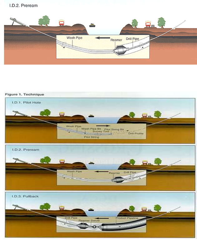
After completing the pilot hole drilling, the drill head and TriHawk bit will be replaced with a reamer (back reamer). Using the rotate–pull technique, the reamer is pulled back towards the drilling rig at a controlled speed appropriate for the geological layers along the bore path. At the same time, drilling fluid of suitable composition is pumped into the borehole to create a tunnel for installing the 20" pipeline.
The reamer enlarges the borehole into a tunnel with sufficient size to successfully pull in the 20” (DN508) steel pipe (minimum 130% of pipe diameter, equivalent to OD 660 mm). Operation of the reamer must follow a procedure calculated based on the geotechnical report to ensure borehole wall stability and to maintain drilling fluid quality inside the borehole for at least 7 days. Maintaining borehole stability and drilling fluid quality is critical to the success of pulling in the OD660 mm pipe, especially for long crossings.
Drilling Fluid for the Project
Drilling fluid is a critical factor in the success of HDD operations. In principle, it is a mixture of water, bentonite, and additives. The bentonite volume is calculated based on geotechnical parameters, borehole diameter, and borehole length.
Functions of drilling fluid:
- Cut, break, and mix soil, rock, and sand in the tunnel when pumped under high pressure.
- Establish and maintain borehole stability (prevent collapse).
- Lubricate the drill head, reamer, and drill rods, reducing heat buildup.
- Transport soil, rock, and sand cuttings out of the tunnel.
- For geological areas with saline contamination or high pH, additives are introduced to minimize performance degradation.
- Another important property of drilling fluid is reusability through recycling equipment.
Pullback of Steel Pipeline D16” with Casing Pipe D20”
The 16” steel carrier pipe will be pulled inside the 20” steel casing pipe through the pre-reamed borehole.
Pullback operations will be performed continuously in one sequence to avoid interruption.
Pipe joints and coating must be inspected prior to pullback to ensure integrity.
During pullback, rollers and padding will be used to protect pipe coating.
Continuous monitoring of pullback force and drilling fluid pressure will be performed to avoid overstress on the pipeline.
Pipe Pullback Technique
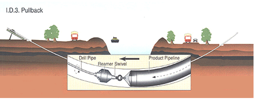
The steel casing pipe is pulled by the thrust force of the drilling rig transmitted through the back reamer, which is connected to a swivel. Using the rotate–pull technique, the pipe string is gradually pulled back toward the rig. Drilling fluid is continuously pumped into the borehole at an appropriate rate to minimize friction on the pipe body and prevent borehole collapse.
The pullback operation must follow a carefully planned schedule based on the bore length and must be executed continuously without interruption. Longer bore paths encounter more geological variations, which increase the risk of overloading the pipe body. Drilling fluid must be calculated precisely to ensure continuous lubrication along the pipeline, reducing the risk of sticking during pullback.
Pullback parameters are often unstable; therefore, the technical supervisor must anticipate load increases and be prepared with contingency measures such as adjusting drilling fluid composition and pullback speed.
If the pullback load increases and corrective action is not taken immediately, the operation must be stopped and the current status maintained. Within 1–2 hours, excess borehole pressure will drop, the tunnel cross-section will shrink, and pipe sticking will occur, drastically increasing drag. Within 7–10 hours, the probability of the pipe becoming stuck is about 90%. After 12 hours without corrective measures, pipe pullback will no longer be possible, requiring the pipeline to be cut and a new bore to be drilled.
Reaming Procedure
After completing pilot hole drilling, the drill head and pilot bit will be replaced with a back reamer. Using the rotate–pull technique, the reamer is pulled back towards the drilling rig at a controlled speed appropriate to the geological conditions, while compatible drilling fluid is pumped to form a tunnel for installing the 20” steel casing pipe (D20”).
The back reamer enlarges the borehole to a size sufficient for successful pipe pullback (minimum 130% of pipe diameter, equivalent to OD 660 mm). Reamer operation must follow a procedure designed based on the geotechnical report to ensure borehole wall stability and maintain drilling fluid quality for at least 7 days. Stability of the borehole and quality of the drilling fluid are critical factors for successful pipe pullback, especially for long crossings.
Reaming sequence:
Remove the drill bit, attach the back reamer and drill rods. Operate the HDD rig to pull back the reamer for hole enlargement.
Continue reaming until the borehole reaches the required diameter for casing pipe installation.
Throughout the reaming process, bentonite drilling fluid is injected to cool and lubricate the reamer and stabilize surrounding soil.
The mud pump simultaneously extracts slurry at the mud pit to prevent water and drilling fluid from flowing back into the borehole.
6. Pipeline Pullback Operation
* General Description
The casing pipe is pulled back by the thrust force of the drilling rig transmitted through the back reamer connected to a swivel. Using the rotate–pull technique, the drill string is gradually pulled back toward the rig. Drilling fluid is pumped into the borehole at an appropriate rate to minimize pipe friction and prevent borehole collapse.
The pullback process must follow a carefully planned schedule suitable for the bore length and must be executed continuously without interruption. The longer the bore length, the more geological variations encountered, resulting in higher stress loads on the pipe. Drilling fluid must be precisely calculated to provide lubrication along the pipe body and reduce the risk of sticking.
Pullback parameters are often unstable; therefore, the technical supervisor must always anticipate increased pull loads and prepare contingency measures such as adjusting drilling fluid composition and pulling speed. If excessive pull load occurs and corrective action is not taken, the borehole pressure will drop within 1–2 hours, the tunnel will gradually shrink, and pipe sticking will occur, drastically increasing drag. Within 7–10 hours, the probability of full pipe lock is 90%, and after 12 hours the pipe can no longer be pulled, forcing the line to be cut and a new bore drilled.
* Pullback Sequence
Weld the pulling head to the 16” product pipe (D16").
Install auxiliary equipment (sandbags, rollers, etc.) to support pipe pullback.
Lift and place the 16” pipe onto supports using a crane.
Attach the reamer to the drill string.
Connect the reamer head to the pulling head of the 16” pipe.
Secure the 20” steel casing pipe (D20") to the 16” pipe using steel straps at 2 m intervals.
Prior to strapping, insert a 6 mm plastic-coated steel cable inside the 16” pipe for future fiber optic cable installation.
The weld joints of the 20” casing pipe shall be offset by 0.5 m from those of the 16” pipe.
Perform steel strap fixing after alignment.
Pull back the 16” pipe with bentonite drilling fluid circulation to provide lubrication.
After pulling approximately 40–50 m, lift and place the second 16” pipe onto rollers using a crane, then weld it to the first section.
After welding, perform Non-Destructive Examination (NDE) using Phased Array Ultrasonic Testing (PAUT).
Apply joint coating once the PAUT inspection is accepted.
Continue connecting the 20” casing pipe to the 16” pipe and perform pullback.
Repeat the above steps for each additional pipe section until the full design length of the 16” product pipe is achieved.
At pit locations, weld connections, perform PAUT inspection, apply joint coating, and apply protective wrapping to the 20” casing pipe.
After pulling in the first 40 m, continue lifting, aligning, welding, inspecting, coating, and pulling subsequent pipe sections until the full designed HDD crossing length is achieved.
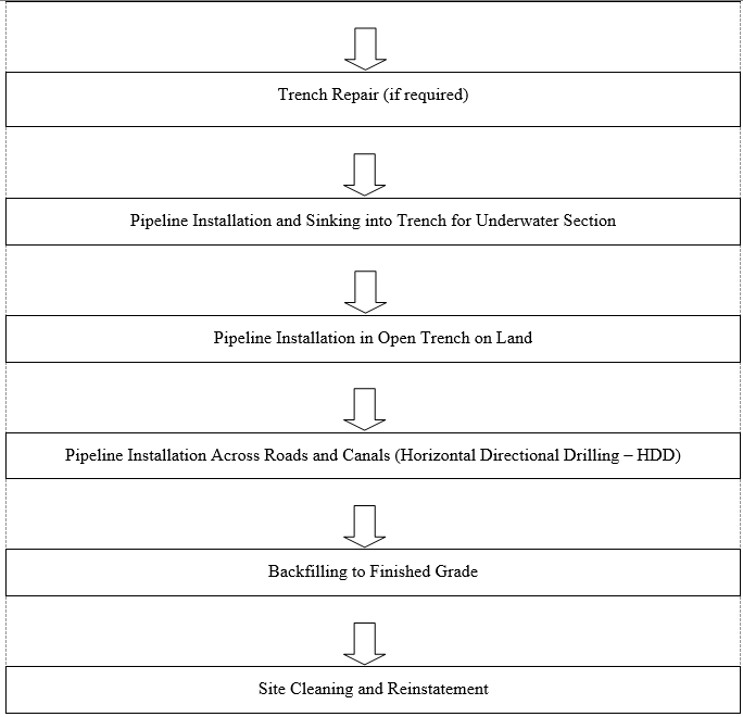
8.5.Site Cleaning and Reinstatement
After completion of pipeline pullback and welding connections, the site reinstatement shall be carried out as follows:
Soil or sand shall be backfilled in layers not exceeding 25 cm in thickness, each layer being compacted to meet design requirements before placing the next layer.
Backfilling shall be performed using a combination of manual and mechanical methods, ensuring safety throughout the operation.
The ground surface shall be restored to the original design elevation of the existing site.
Sidewalks shall be reinstated to their original condition.
Grass shall be replanted to match the original landscape condition.
Surplus soil and rocks after reinstatement works shall be transported away from the site.
9.0.Measures for Traffic Safety, Environmental Sanitation, Fire Prevention and Fighting, and Site Security
9.1.General Provisions
The Contractor shall establish a dedicated division responsible for organizing and supervising occupational safety in compliance with construction safety regulations.
At the site, a signboard shall be posted displaying the project name, Contractor’s name, and the site regulations on occupational safety.
All staff and workers must be trained in site regulations, occupational safety, and fire prevention and fighting procedures before commencing work.
The construction procedures shall be introduced to nearby households and units adjacent to the site, with special attention to high-risk activities and the preventive measures adopted by the Contractor.
In the event of an incident, the Contractor must immediately notify the relevant authorities and promptly organize emergency response using available on-site resources.
9.2.Site Security
A site security team shall be established to coordinate closely with local security forces in setting site regulations and conducting regular patrols around the construction area.
Working hours shall be strictly controlled; only workers with work-related requirements are permitted to leave the site premises in order to avoid disruption of operations.
All staff and workers recruited for the project must have a clear background record, with no history of disciplinary violations or breaches of company regulations.
Any individual causing public disorder or colluding with undesirable external elements shall be subject to immediate dismissal.
9.3.Environmental Sanitation
During the construction process, environmental impacts may occur, including the following sources of pollution:
- Dust pollution from soil and rock, directly affecting workers on site;
- Pollution from waste emissions of transport vehicles and construction machinery;
- Noise pollution generated by transport vehicles and construction machinery.
- To mitigate these impacts, the following measures shall be implemented:
- Daily site cleaning: one dedicated worker team shall be assigned each day to regularly collect and remove trees, wooden planks, scrap materials, debris, etc. Construction equipment and materials shall be returned to the warehouse or placed in designated areas after each working day;
- Excess soil management: surplus soil generated during construction shall be transported out of the site by the Contractor and disposed of at authorized dumping locations in accordance with regulations.
9.4.Fire and Explosion Prevention, Internal Traffic Safety
Fire prevention and fighting (FPF) is prioritized throughout the construction process. Fire prevention consists of organizational and technical measures to prevent fire outbreaks, limit fire spread, extinguish fires effectively, and ensure safe evacuation of people and protection of property.
Strict compliance with traffic safety procedures shall be maintained during the entire construction period within the site.
Fire safety regulations for the gas pipeline shall be disseminated to all staff and workers involved in construction.
At least two fire extinguishers shall always be available at the construction site.
Smoking is strictly prohibited for all staff and workers at the construction site.
Emergency hotlines of local fire-fighting units shall be posted for immediate contact in case of incidents.
a. Organizational Measures
Educate, train, and motivate all employees to comply with national fire prevention and fighting laws, regulations, and site fire safety rules through training sessions, drills, and signage.
Conduct site-wide dissemination and training of fire prevention and fire-fighting procedures for all workers.
b. Technical Measures
Provide fire-fighting equipment and instructions at designated points.
Areas storing flammable materials (e.g., fuels, gas cylinders, pressurized equipment) must:
Maintain safe separation distances.
Be fenced off with “No Fire/No Unauthorized Entry” signage.
Be equipped with suitable fire-fighting facilities (fire extinguishers, water tanks, sand).
No electrical systems shall be installed across flammable material storage areas.
Electrical safety must be strictly observed: circuit breakers, switches, and fuses must be in accessible, protected boxes with warning signs.
c. Prohibited Practices
Smoking or drinking alcohol during working hours within the construction site.
Use of fire, sparks, or welding in prohibited areas or near combustible materials.
Welding/cutting in areas with high accumulation of flammable materials.
Storage of combustible materials must be downwind and at lower elevations with adequate fire separation distances.
Emergency Response
In case of fire, the site security team must immediately notify the Fire Police (dial 114).
Workers shall be organized for initial fire-fighting efforts.
Regular inspections shall be conducted to ensure sufficient fire-fighting equipment and water sources (natural reservoirs or tanks).
Site roads must remain wide and clear for fire trucks to access both the fire area and nearby water sources.
9.5.Occupational Safety
Safety for personnel, equipment, and materials shall be ensured throughout the preparation and construction phases.
Safety of the constructed works and adjacent structures must always be protected.
During construction, strict compliance with “Technical Safety Regulations in Construction” (TCVN 5308-91) is mandatory.
All site staff and workers must attend safety training sessions in accordance with Circular No. 08 and Circular No. 23 of the Labor Code, and comply with Decree 06/CP of the Government as well as Chapter 9 of the Labor Code. This is a compulsory requirement. Each individual must sign the attendance record before being allowed to work.
A dedicated Safety Officer shall be assigned at the site, supported by a safety network consisting of engineers, team leaders, and supervisors. An Occupational Safety Logbook shall be maintained.
Workers and staff shall attend construction safety training classes conducted by the Safety Officer.
Prevent and minimize hazardous and harmful factors that could cause accidents, occupational diseases, or health issues.
Comply with occupational safety and hygiene regulations. Maintain an Occupational Safety Diary, and perform proper reporting, investigation, and analysis of all accidents and occupational diseases. Strict compliance with safety rules is required when working within the pipeline safety corridor.
Workers employed at the construction site must meet all job requirements regarding age, gender, health, skill level, and safety training certification.
Provide adequate welfare facilities for workers: sanitary toilets, shelters against sun and rain, clean drinking water, first aid and emergency care stations.
Safety personnel shall be present regularly on-site to inspect and remind workers to comply with occupational safety rules.
Workers must be equipped with at least the following Personal Protective Equipment (PPE): safety boots, helmets, goggles, gloves, and contractor-specific uniforms.
All electrical equipment and wiring used at the site must be inspected and certified safe before being put into operation.
CÔNG TY CP TƯ VẤN ĐẦU TƯ & THIẾT KẾ XÂY DỰNG MINH PHƯƠNG
Địa chỉ: Số 28B Mai Thị Lựu, Phường Đa Kao, Q.1, TPHCM
Hotline: 0903649782 - (028) 3514 6426
Email: nguyenthanhmp156@gmail.com
Tin tức liên quan
2321 Lượt xem
This purpose of this document is to describe in general terms the HDD process and methodologies that will be utilized for “Approximately 94 km of 30-inch onshore pipeline from An Minh Landfall Station to O Mon Gas Distribution Center (GDC) at Can Tho Province” section this project.
1714 Lượt xem
Execution plan for horizontal directional drilling gas pipeline project. This execution plan is proposed according to the work list which is provided by EPC as well as all the HDD geological condition are considered as the normal soil, and the HDD list is as followed.
1457 Lượt xem
Construction Method for Horizontal Directional Drilling (HDD) of the Gas Pipeline. Present the horizontal directional drilling method for the project, general construction organization methods, on-site construction organization, construction site layout, quality control measures, applicable technical standards, and construction sequence.
1782 Lượt xem
The purpose of this document is to propose a method for the Project Management Consultant and the Investor to review and approve for the Contractor to execute and control the drilling process for pulling a steel pipe with a diameter of D200 under the road.
6202 Lượt xem
This document has been prepared to describe the methodology by which MCD/HDDT propose undertaking the site preparation, mobilization, drilling operations, pipe installation, pre-commissioning and reinstatement operations for the installation of the 6 HDD crossings on the Block B Omon Project - Onshore Pipeline.
2337 Lượt xem
Pipe Jacking Project of Vietnam Vung Ang II power plant. Dự án thi công khoan đường ống nhà máy nhiệt điện Vung Ang II.
Xem thêm