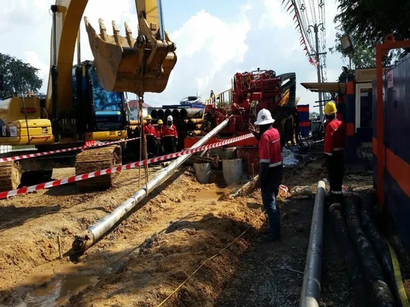
Pipe Jacking Project of Vietnam Vung Ang II power plant
Pipe Jacking Project of Vietnam Vung Ang II power plant. Dự án thi công khoan đường ống nhà máy nhiệt điện Vung Ang II.
Pipe Jacking Project of Vietnam Vung Ang II power plant
Dự án thi công khoan đường ống nhà máy nhiệt điện Vung Ang II. Analysis of Pipe Jacking Construction. Tư vấn thi công khoan ngầm - khoanngam.net. Hotline 0903 649 782.
I Analysis of the influence of pipe jacking construction on the surrounding environment
As a trenchless underground engineering construction method, pipe jacking has high applicability. There are not many restrictions on the construction environment during the pipe jacking construction, and the impact on the ground environment is small. However, pipe jacking construction will cause stratum loss, which will have different effects on the surrounding environment according to the difference of construction method and pipe diameter. During pipe jacking construction, both single pipe jacking and parallel pipe jacking may occur. During the parallel pipe jacking construction, in addition to the impact on the surrounding environment, the later pipe jacking will have varying degrees of impact on the first pipe jacking according to the different construction units. According to the construction organization and site conditions of pipe jacking Project of Vung Ang II power plant in Vietnam, this report makes a theoretical analysis of the pipe jacking construction of this project by using the analysis method of numerical simulation under different construction conditions, in order to provide reference for pipe jacking construction.
1. Basic assumptions
The composition of rock and soil is very complex, so it is very difficult to simulate the stiffness characteristics of geotechnical materials completely. When the purpose of the analysis is clear, it is necessary to simplify the analysis model properly. For this reason, according to the actual situation and characteristics of the project, the following assumptions and simplifications are made in the analysis:
a. Simplify the soil layer into an isotropic, homogeneous continuous material. Based on the macroscopic material behavior, the Mohr-Coulomb elasto-plastic model is used for the rock and soil mass, and the soil mass is simulated by a plane strain element. Simplify the surface and each layer of soil to make it a homogeneous horizontal layered distribution.
b. In the model calculation, the initial in-situ stress only considers the self-weight stress of the soil body, and does not consider the influence of groundwater; it is assumed that the pipe jacking segment is formed at one time, and the settlement is stable after construction. Reset the initial state.
c. 340mm thick concrete segment is mainly considered in the model.
d. For the stratum parameters selected in the model, refer to the soil parameters given in the engineering geological prospecting report, and refer to the Geological Engineering Manual when specific data is lacking.
e. The load is divided into two parts: dead load and live load: dead load is self-weight, and the self-weight of segment is automatically calculated by software; live load is considered according to driving load.
2. Model size and boundary conditions
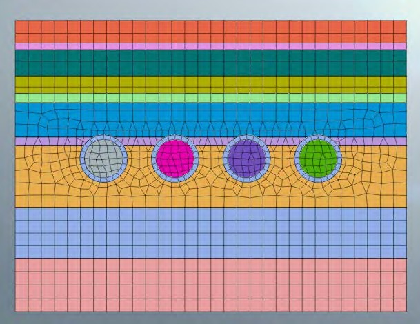
Combined with engineering experience and theoretical analysis, a 2D model is adopted. The size of the model is set as the left and right widths of 30.3m (X direction) and the thickness of 22.5m (Y direction). According to the latest borehole BH2, the soil layer is divided into 6 layers, the first layer is 4.3 m thick 1 sandy clay, the second layer is 4.5m thick 5 silt, the third layer is 0.9m thick 6a clay, the fourth layer is 4.8m thick 6b clay, and the fifth layer is 3.9m thick 9 sand The sixth layer is a 4.13m thick 10-strong weathered bedrock; the main strata of the pipe jacking are 5 silt, 6a clay and 6b clay, and there are 4 parallel jacking pipes with an inner diameter of 3m and an outer diameter of 3.68m. The clear distance between jacking pipes is 1.85m.
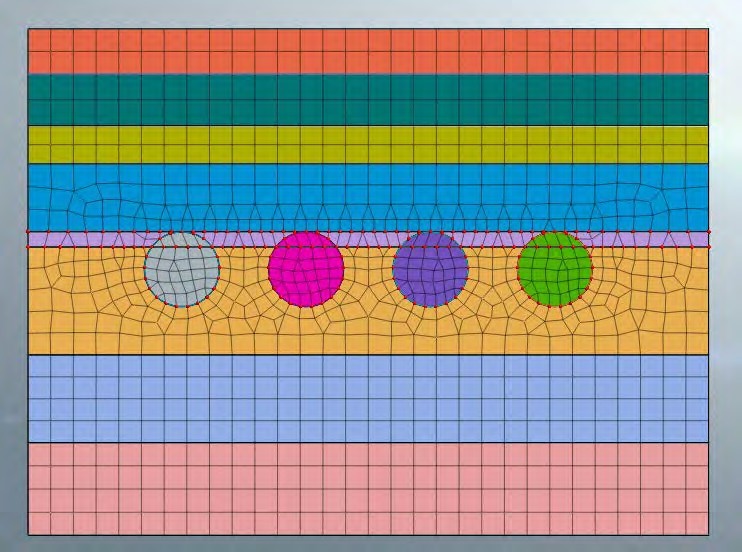
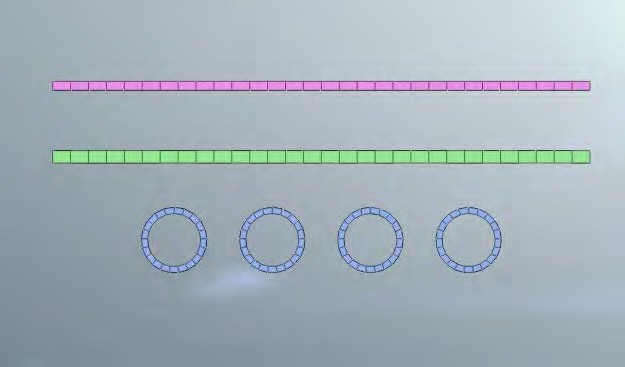
The upper surface of the model is free constraint, the bottom is fixed constraint, and the surrounding is normal constraint, and the mesh size around the segment is controlled, and the mesh around the segment is encrypted, so that the segment can be analyzed more accurately, as shown in Figure 1.2. 2. The final model is shown in Figures 5.3.1~5. Finally, 144 1D attribute grids and 1033 2D attribute grids will be established.
Figure 1.2.1 Numerical 2D grid. Thi công khoan ngầm
Figure 1.2.2 Schematic diagram of numerical 2D grid control
Figure 1.2.3 Numerical 2D model diagram (pipe jacking segment and roof and floor of the box culvert)
3. Selection of parameters
Công nghệ khoan ống ngầm. Bảng giá thi công khoan ống ngầm cho nhà máy
The material parameters are combined with the soil layer parameters provided by the Mohr-Coulomb model used in this numerical simulation, and the selection principles are as follows:
a. The cohesion, internal friction angle, gravity and elastic modulus are set according to the physical and mechanical indicators provided by the geology combined with the empirical parameters;
b. Beam elements are used to simulate the top, bottom and pipe jacking segments of the box culvert, and the parameters are set according to the concrete grade used.
c. In this simulation, combined with the geological data of the crossing area, the influence of groundwater is not considered in the calculation.
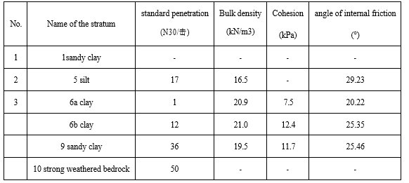
According to the geological parameters in the geological prospecting report and with reference to similar projects, the mechanical calculation parameters are selected. The specific parameters are shown in Table 4.3.3-1~2. The first layer is 4.3m thick 1 sandy clay, the second layer is 4.5m thick 5 silt, the third layer is 0.9m thick 6a clay, the fourth layer is 4.8m thick 6b clay, and the fifth layer is 3.9m thick 9 sandy clay, and the sixth layer is 4.13m thick 10 strong weathered bedrock. The mechanical parameters are shown in the table below, among which 1 sandy clay layer geological
exploration report has no detailed parameters, and the values are selected according to past experience in the model simulation.
Table 4.3.3-1 physical and mechanical parameters of formation
4. Analysis of the impact of pipe jacking construction
The parallel pipe jacking construction is divided into 8 construction steps, 4 parallel pipe jacking constructions are carried out at intervals, and the pipes are numbered No.1, No.2, No.3 and No.4 in sequence from left to right, and pipe jacking construction is carried out in the order of No. 1, No. 3, No. 2 and No. 4.
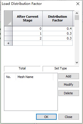
Each pipe jacking construction is divided into two construction steps. The first construction step is to excavate the inner soil of the segment, and the second construction step is to apply the pipe jacking segment. By controlling the load release coefficient of these two construction steps (such as Figure 1.4.1, according to the previous design experience, 40% of the stress is released in this stage of the pipe jacking construction, and 30% is released at each stage in the next two construction steps), which simulates the on-site pipe jacking construction more realistically.
Figure1.4.1 Load Distribution Factor. Dịch vụ khoan ngầm robot
The construction steps are as follows:
Step 1: the stress is in the initial state, the mesh, gravity and constraints are applied, and the displacement is cleared.
Step 2: Excavate the soil inside the No. 1 jacking pipe.
Step 3: carry out the construction of the No. 1 pipe jacking segment.
Step 4: Excavate the soil inside the No. 3 jacking pipe.
Step 5: carry out the construction of the No. 3 pipe jacking segment.
Step 6: Excavate the soil inside the No. 2 jacking pipe.
Step 7: carry out the construction of the No. 2 pipe jacking segment.
Step 8: Excavate the soil inside the No. 4 jacking pipe.
Step 9: carry out the construction of the No. 4 pipe jacking segment.
In this chapter, through numerical simulation analysis, the results of box culvert deformation, pipe jacking segment deformation and land subsidence are obtained. The analysis results are as follows.
4.1 Analysis of Box Culvert Deformation
Figure 4.1.1 Construction step 2 - deformation cloud map of box culvert
Figure 4.1.2 Construction step 3 - deformation cloud map of box culvert
Figure 4.1.3 Construction step 4 - deformation cloud map of box culvert
Figure 4.1.4 Construction step 5 - deformation cloud map of box culvert
Figure 4.1.5 Construction step 6 - deformation cloud map of box culvert
Figure 4.1.6 Construction step 7 - deformation cloud map of box culvert
Figure 4.1.7 Construction step 8 - deformation cloud map of box culvert
Figure 4.1.8 Construction step 9 - deformation cloud map of box culvert
Table 4.1.1 Summary of Box Culvert Deformation
It can be seen that the maximum cumulative displacement of the box culvert during the pipe jacking construction is 3.32mm, which occurs in construction step 9, that is, after the construction of No. 4 pipe jacking is completed, which meets the requirements.
4.2 Analysis of the deformation of the pipe jacking segment
Segment construction occurs in construction steps 3, 5, 7, and 9, and only these four construction steps are analyzed.
Figure 4.2.1 Construction step 3 - deformation cloud map of segment
Figure 4.2.2 Construction step 5 - deformation cloud map of segment
Figure 4.2.3 Construction step 7 - deformation cloud map of segment
Figure 4.2.4 Construction step 9 - deformation cloud map of segment
Table 4.2.1 Summary of the deformation of the jacking segment
It can be seen from the figure that the maximum displacement of the segment during construction is 4.864mm, which occurs in the construction step 9, and the displacement of the No. 2 pipe jacking segment is the largest, which meets the requirements.
4.3 Analysis of Ground Settlement
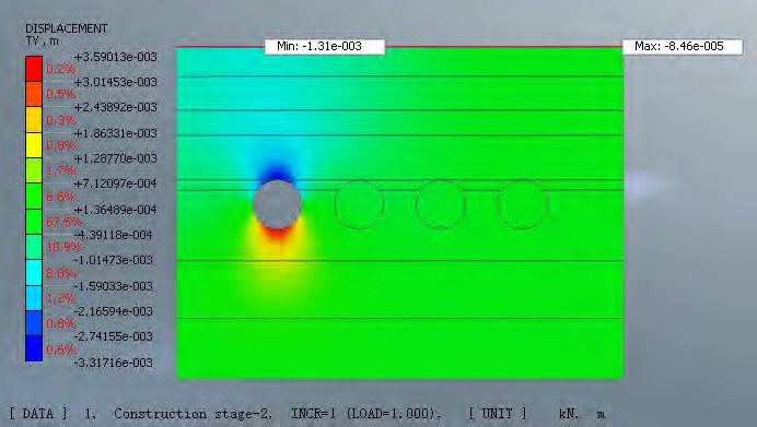
Figure 4.3.1 Construction stage 2- Ground Settlement Cloud Map
Figure 4.3.2 Construction stage 3 - Ground Settlement Cloud Map
Figure 4.3.3 Construction stage 4 - Ground Settlement Cloud Map
Figure 4.3.4 Construction stage 5 - Ground Settlement Cloud Map
Figure 4.3.5 Construction stage 6 - Ground Settlement Cloud Map
Figure 4.3.6 Construction stage 7 - Ground Settlement Cloud Map
Figure 4.3.7 Construction stage 8 - Ground Settlement Cloud Map
Figure 4.3.8 Construction Stage 9 - Ground Settlement Cloud Map
Table 4.3.1 Summary of Ground Settlement
The maximum ground settlement occurs at the pipe-jacking construction site, and the ground settlement is less than that at the construction site, which conforms to the stress diffusion principle. The maximum ground settlement value is 3.3mm, which meets the requirements of ground settlement control.
1. Conclusion
By the means of numerical analysis (Midas GTS NX software), basing on the design document, the following conclusions are drawn through analysis:
a. Pipe-jacking construction: four parallel pipes jacking with interval construction method will be operated in this work, and the mutual influence between pipe jacking is controllable. The influence on the underpass box culvert about the deformation meets the requirements, the ground settlement value meets the requirements and the construction scheme is feasible after analysis and design.
b. Geological conditions
The pipes jacked in this project mainly passes through the stratum layer 5 silty sand, 6a clay and 6B clay. According to the geological survey report, the numerical simulation analysis is carried out on the parameter values of different stratum. The analysis results show that the pipe-jacking in the local stratum meets the deformation control requirements.
c. Evaluation of Engineering measures
i. The pipe jacking construction adopts interval construction method, which reduces the mutual influence caused by adjacent pipe jacking construction, and the construction scheme meets the safety requirements
ii. As safety measures, starting reinforcement and ground layer reinforcement can ensure the safety in the process of pipe jacking construction. Grouting pressure should be strictly controlled in the process of reinforcement to ensure that the grouting process does not affect the surrounding structures.
In conclusion: according to the design assumptions and theoretical calculation, on the basis of the existing design scheme, the construction will be carried out by interval pipe jacking with starting reinforcement and ground layer reinforcement. In this way, the surrounding environment and the deformation control of architectural structures can meet the requirement. The comprehensive evaluation of design and construction scheme is feasible and the construction technologies meet the design requirements,
2. Suggestion
By checking calculation, the influence of pipe jacking construction on surrounding environment and construction structures meets the requirements.
Matters need attention in construction:
Considering that the theoretical numerical calculation is simulated in the ideal state, the uncertainty and unpredictability of underground engineering construction also exist in the actual construction process, thus the calculation results only play a qualitative and semi-quantitative role. The following technical measures should also be taken during construction to ensure construction safety.
a. During the whole process of pipe jacking, the forward direction of the tool pipe should be controlled, and the cause and development trend of the deviation should be analyzed according to the measurement results, and corrective measures should be determined. The deviation should be corrected in the jacking process and gradually corrected by small angle.
b. It is necessary to strengthen the observation and recording of the geology of the excavation working face, and to judge its stability and forecast the geological conditions in front of the excavation, so as to guide the construction. If necessary, effective measures such as ground grouting or cave grouting should be taken to ensure the stability of the working face
c. Sufficient pumping and drainage measures shall be provided on site to ensure no water operation for pipe jacking construction
d. Due to the complexity and changeful engineering geology and hydrogeology, there are many unsafe hidden dangers, including poor construction environment and working conditions. it is necessary to strengthen monitoring during construction process and take timely measures to eliminate hidden dangers. It is also necessary to strengthen construction ventilation to eliminate harmful gases, cool down, dehumidify, eliminate hypoxia and maintain fresh air so as to improve the working environment, and ensure safety.
Xem thêm: Mẫu phân công lịch trình công trình xây dựng - Schedule of CW Pipe Underpass VA1 Facility
CÔNG TY CP TƯ VẤN ĐẦU TƯ & THIẾT KẾ XÂY DỰNG MINH PHƯƠNG
Địa chỉ: Số 28B Mai Thị Lựu, Phường Đa Kao, Q.1, TPHCM
Hotline: 0903649782 - (028) 3514 6426
Email: nguyenthanhmp156@gmail.com



Xem thêm