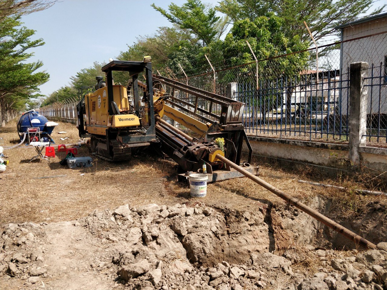
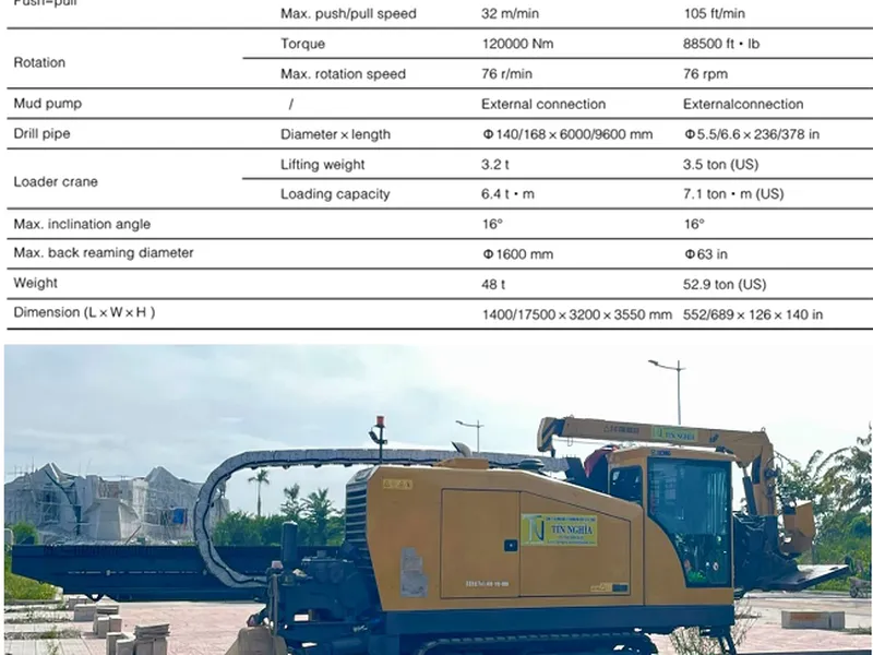
Horizontal directional drilling technology
All horizontal directional drilling job shall be performed in strict accordance with all governing federal, state, and local regulations. The horizontal directional drilling HDD operations shall be conducted in accordance with the latest approved editions of the following referenced documents where applicable:
TABLE OF CONTENTS
1. Code, Specifications, and Standards
2. Acronyms
3. Protection of underground structures
4. Plan and Procedure
5. Responsibilities of the HDD Contractor
6. Priority, Workspace, and Access
7. Environment
8. Safety
9. Requirements for horizontal directional drilling
10. Pipe installation and Back pull operations
11. Maritime Assistance
12. Final Construction Report
13. Backfill and Site Restore
Attached revision log/log
1. CODES, SPECIFICATIONS, AND STANDARDS
All horizontal directional drilling job shall be performed in strict accordance with all governing federal, state, and local regulations. The horizontal directional drilling HDD operations shall be conducted in accordance with the latest approved editions of the following referenced documents where applicable:
1.1 Pipeline and Hazardous Materials Safety Administration (PHMSA)
|
49 CFR 192 |
Transportation of Natural and Other Gas by Pipeline |
|
49 CFR 195 |
Transportation of Hazardous Liquids by Pipeline |
1.2 American Petroleum Institute (API)
|
API 1104 |
Welding of Pipelines and Related Facilities, 20th Edition |
|
API Bulletin D20 |
Directional Drilling Survey Calculation Methods and Terminology |
|
API RP 13B/ISO 10414-1 |
Recommended practice for field testing water-based drilling fluids. |
|
API RP 13D |
Rheology and hydraulics of oil-well drilling fluids. |
|
Specification 13A/ISO 13500 |
Specification for Drilling Fluids Materials |
1.3 American Society of Mechanical Engineers (ASME)
|
B31.4-2006 |
Pipeline Transportation Systems for Liquid Hydrocarbons and Other Liquids |
|
B31.8-2007 |
Gas Transmission and Distribution Piping Systems |
1.4 International Association of Drilling Contractors (IADC)
|
IADC |
Drilling Manual |
1.5 Standards and horizontal directional drilling specifications
|
STD.4507 |
Pipeline Hydrostatic Testing |
|
STD.7002 |
Protective Coatings – Below Ground Steel Surfaces – Field Applied |
|
STD.8700 |
Pipeline Construction - Onshore |
2. ABBREVIATIONS
|
Terms |
Definitions |
|
ECP |
Environmental Construction Plan |
|
COE |
Corps of Engineers |
|
HDD |
Horizontal Directional Drilling |
|
HDPE |
high-density polyethylene |
|
MSDS |
Material Safety Data Sheet |
|
ROW |
Right-of-Way |
|
SWPPP |
Storm Water Pollution Prevention Plan |
|
SPCP |
Spill Prevention Control Plan |
|
FBE |
Fusion Bonded Epoxy |
3. PROTECTION OF UNDEGROUND FACILITIES
1) Contractor shall undertake the following steps prior to commencing drilling operations in a location that might contain underground facilities.
a) Contact the utility location/notification service (One Call), if available, for the construction area. Records of the appropriate "one calls" shall be kept for the duration of construction. If, after initiating the "one call" process, there are known facilities in the area that have not been marked, the owner/operator shall be contacted to mark their facility.
b) Positively determine the location and depth of and stake all existing lines, cables, or other underground facilities including exposing any facilities that are located within 15 feet of the designed drilled path.
c) Modify drilling practices and downhole assemblies to prevent damage to existing facilities.
2) Contractor shall be responsible for locating all underground facilities regardless of Company previous efforts in this regard. Contractor shall be responsible for all losses and repairs occasioned by damage to underground facilities resulting from drilling operations.
4. PLANS AND PROCEDURES
4.1 Prior to Award of Contract
Preliminary data shall be submitted with the proposal in sufficient detail for Company to evaluate the compliance of the proposed directional drilling plan with the specification, Corps of Engineers (COE) permit and other governmental regulations.
4.2 Prior to Commencement of Work
Contractor shall submit written descriptions of equipment, methods, and procedures for completion of the Work prior to commencement of Work. Equipment descriptions shall include model, date of manufacture, and data sheets including capacities and ratings. Methods and procedures shall include descriptions of approach to the Work and individual procedures required to affect the overall method. As part of this requirement, Contractor shall show the plan of the drill site equipment layout, including location of erosion and sediment control devices, water, drilling mud treatment equipment, design profile drawings, etc., and a site specific safety program to protect Contractor and Company personnel, the public and the environment.
1) Contractor shall submit an execution plan with scope of work and schedule, design profile drawings, and detailed procedures to Company for approval prior to commencing Work for the following operations as applicable for marine and land HDD:
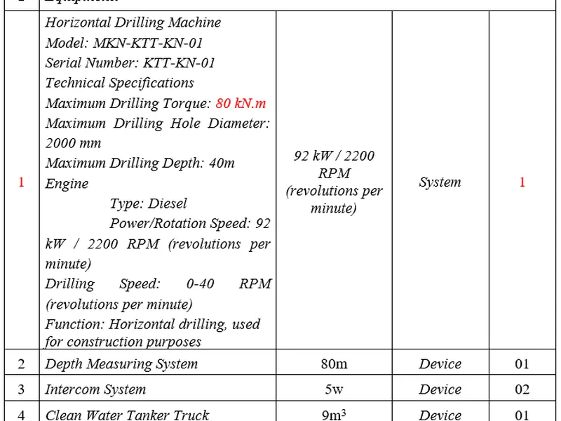
- Type and size of drilling rig
- Type and size of drill pipe
- Type and size of rollers and other support equipment
- List of other equipment to be used
- Procedures for excavation of entry and exit transition trenches, including type of vessels, expected production rate, and method of retaining resultant spoil to be used for marine trenching
- Mud plume discharge control during excavation and directional drilling
- Pilot hole drilling procedure
- Reaming operation
- Mud system and control
- Buoyancy control
- Pullback procedure
- Type of drilling fluid including additives
- Inadvertent discharge control
- As applicable for onshore worksites, drilling fluid disposal including name and location of off-site facility
- Directional drilling profile, pipe stress calculations, drawings, and method for monitoring the borehole profile
- Procedures for directional drilling of the crossing, including design profile, specified limits on pressures, tensions, sea-state motion, flow, or other limits within the capabilities of Contractor's equipment
- Method of monitoring drilling progress
- Procedures for positioning of the pipeline and pull back of the pipeline in the crossing
- Maximum variance expected during directional drilling due to variations in mud types, weights, and flow capacities
Procedures for ensuring stability of the pipeline at the transition areas until the final tie- ins are completed
All procedures or material descriptions requiring Company approval must be submitted by the Contractor a minimum of ten days prior to commencing any HDD activities at the proposed crossing locations. The work shall not commence until said documentation has been approved by Company and lack of Contractor-obtained approval shall not constitute grounds for extra work claims by Contractor.
5. HDD CONTRACTOR RESPONSIBILITIES
1) Contractor shall provide all necessary labor, supervision, professional and technical services, installation plans and procedures, plants and equipment, vessels, materials (except where stated otherwise in the "Company-supplied Materials" list), consumables, inspections, surveying, diving, testing, mobilization/demobilization transportation, and shall perform the Work described in the Scope of Work including, but not limited to the following:
a) Clearing, grading, and general site/access preparation necessary for construction operations, including installation of all turbidity mitigation structures (if required) and excavation of entry and exit holes.
b) Transportation of all equipment, labor, consumables, and Company supplied materials, including pipe and appurtenances, to and from the jobsite.
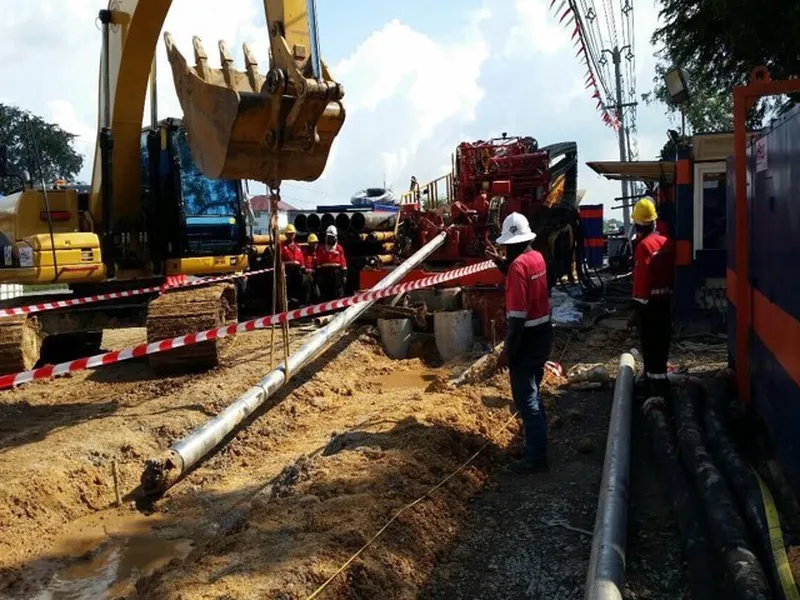
c) Erection of horizontal drilling equipment at the rig sites defined on the Drawings.
d) Drilling of a small diameter pilot hole along the path defined on the Drawings.
e) Reaming the pilot hole to a diameter suitable for installation of the prefabricated pull section.
f) Prefabrication of the pull section.
g) Hydrostatically pre-testing the fabricated pipe pull section before pullback.
h) Installation of the prefabricated pull section in the reamed hole.
i) If applicable, the marine pipeline installation contractor is responsible for tie-in of the marine end of the HDD segment to the pipeline system after completion of the final HDD hydrostatic test.
j) Clean up and restoration of all work areas, including removal of installation aids and backfilling of entry and exit holes.
2) Contractor shall comply with the requirements of all permits issued by Federal and/or State Regulatory Agencies.
3) Contractor shall for the duration of the Work, assign the necessary qualified and experienced personnel, equipment, work areas, craftsmen, supervision, tools, and all other materials and supplies to meet Project milestones. Key personnel shall be identified in Contractor's bid proposal. A qualified HDD Superintendent, approved by Company, shall directly supervise construction at all times. At no time shall other work pre-empt Work being performed for Company, without Company written consent. Contractor shall not reassign key project personnel and/or equipment or vessels from Work being performed for Company without Company written consent.
4) Contractor shall work such hours, including extra shifts and overtime, necessary to meet the Contract Schedule specifically including the field coordination necessary to accommodate pull-back of the pipeline string fabricated and tested by others. Contractor and its Subcontractors shall accept the presence of Company Representatives on its premises, facilities and vessels for the purpose of coordination, inspection, monitoring, and review of any aspect of the Work.
5) All vessels and equipment required to perform the Work in State waters will be required to meet the "Zero Discharge" requirements. Contractor shall develop plans and procedures unique to onshore and offshore construction as designated by regulatory bodies.
6. RIGHT-OF-WAY, WORKSPACE, AND ACCESS
1) All Contractor and equipment must stay within the designated right-of-way, access roads, and workspace as shown in the construction drawings. No work is allowed outside of the right-of- way and workspace. The Contractor shall set up all necessary equipment, personnel and materials, set up work areas on the entry and exit sides of the crossing, and prepare the sites for construction. The Company will mark the construction workspace and sensitive area boundaries. The Contractor shall not go outside the provided workspace or disturb any sensitive area. The Contractor shall meet the requirements and/or stipulations of each landowner in accordance with the Right-of-Way (ROW) Line List.
2) If additional workspace is required for an onshore worksite, Contractor shall prepare a written request including drawings that describe the extent of the workspace requested and a compelling argument that clearly demonstrates the need for the additional workspace. Any expense associated with acquiring additional workspace shall be the responsibility of the Contractor. The Contractor is advised that the acquisition of additional workspace will be subject to review by the various permitting agencies. The Company will make an effort to acquire the requested workspace; however, the Company cannot guarantee the timely approval of the request.
3) All access roads and routes, both public and private, shall be prepared and maintained by the Contractor. The Contractor shall restore access roads to their original condition. This work shall meet with the approval of the applicable land owner(s) and/or agencies.
7. ENVIRONMENTAL
Environmental concerns addressed within this section include those actions necessary to execute the Work, including reduction of impacts to the surrounding water and land, regulatory impacts, and general public impacts.
7.1 Work Space
1) Dewatering, including storm water, shall be completed per the Storm Water Pollution Prevention Plan (SWPPP).
2) All trash, removed vegetation, and waste shall be removed from the site and disposed of in a manner acceptable to the Company.
7.2 Water Supply
Contractor shall procure and transport water for drilling operations and hydrostatic testing from sources approved by the Company.
7.3 Hydrostatic Test Water Discharge
All hydrostatic test water shall be treated by Contractor to satisfy the SWPPP and all applicable permit requirements and discharged at a Company approved site. At no time shall discharge cause soil erosion, bottom sediment disturbance, nor affect safety.
7.4 Bentonite
Technical criteria for bentonite shall be as given in API Spec. 13A. The composition of all drilling fluids proposed for use shall be submitted to Company for approval. Drilling fluids shall comply with all applicable permit requirements and environmental regulations.
7.5 Drilling Fluids and Cuttings Disposal
Waste cuttings and drilling fluids shall be disposed of by Contractor at a Company approved disposal site. The construction areas will be checked a minimum of twice daily for signs of unplanned leaks or seeps.
A written record shall be maintained by the Contractor of all inspections and submitted with his daily report to the Company Representative.
7.6 Sanitation Facilities
Contractor shall provide portable toilets, garbage containers, and services to empty and clean these facilities at all work sites. Waste shall be transported off-site for disposal.
7.7 Refueling and Equipment Maintenance
1) All activities involving fuels and lubricants shall be performed in accordance with the Contractor's Spill Prevention Control Plan (SPCP).
2) Both the Pipeline Installation Contractor and the HDD Subcontractor shall satisfy the requirements of appropriate regulatory agencies by providing a means to contain, monitor, and abate turbidity (if required) in the marine environment while performing HDD's, including to the maximum possible extent, the capture and containment of any drilling mud/fluids that may escape the HDD holes.
3) Contractor shall provide all appropriate means to suppress the sound level at onshore residential and business areas to a level that will not disturb the occupants of those areas. These noise suppression means shall include but shall not be limited to sound -reducing engine exhaust systems, enclosing the engines and equipment in tents, and temporary acoustic walls between the occupied buildings and the work site.
4) Contractor shall comply with all the environmental and erosion and sediment control requirements. An Environmental Response Team shall be formed to respond to changing environmental conditions and emergencies. Examples where an Environmental Response Team would be required include:
- Potential sedimentation or watercourses, wetlands, or waterbodies as a result of rainfall
- Earthen berm failure
- Inadvertent discharges
- Zero Discharge violation from marine vessel
5) The Environmental Response Team shall be available on a 24 hour basis and be responsible for responding to and implementing the necessary remedial action.
8. SAFETY
1) The safety of the general public, Contractor personnel, and Company personnel is of paramount importance. No construction activity shall occur which in any way compromises a safe operation. The Contractor shall at all times provide for the safety of all pipeline construction personnel and the general public during drilling operations by doing the following:
- Restricting access to the immediate area involving the drilling operation to only those personnel engaged in the actual operation of the drilling equipment, Company Inspectors, and Company visitors that have been subject to a safety presentation.
- Prohibiting pipeline work in or around the drilling site not directly associated with the drilling operation.
- Providing and installing construction warning signs as necessary in the vicinity of the work site.
2) The Contractor shall comply with all applicable laws, orders, regulations, and ordinances, whether Federal, State, County, or Local, pertaining to safety. Adherence to these regulations shall be mandatory in and around all Company workplaces, including off right-of-way sites that the Contractor set up as part of the overall project. Personal protective equipment shall be worn at all times. The equipment shall include safety shoes, hard hats, and eye protection and hearing protection as needed.
8.1 Entry Side
The Contractor shall remove fences, trees, shrubs, trash, and debris, and set up workspace shown on plan and profile drawing. Contractor shall, at a Company approved site, dispose of all timber, stumps, and rock as required to not impede construction activity. Contractor shall not damage those trees marked and/or fenced by Company on and/or adjacent to the workspace. The area shall be graded and a 12 in. high containment berm built around the mud pit or as required by permits. The site shall contain the horizontal drilling rig, pipe storage racks, mud pumps, primary pickup pits, mud tank, shaker/desander- desilter, disposal pits, water cleaning equipment, dry storage area for drilling fluid additives (etc.), offices, a crane area, and parking facilities.
8.2 Exit Side Including Pipe Stringing Area
The Contractor shall remove fences, trees, shrubs, trash, and debris, and set up a temporary work area as shown on plan and profile drawing. Contractor shall, at a Company approved site, dispose of all timber, stumps, and rock as required to not impede construction activity. Contractor shall not damage those trees marked and/or fenced by Company on and/or adjacent to the workspace. The area shall be graded and a 12 in. high containment berm built around the mud pit or as required by permits.
9. DIRECTIONAL DRILLING REQUIREMENTS
9.1 General
1) Contractor shall ensure that all HDD operations are performed utilizing supervisors and construction personnel thoroughly experienced in HDD. All required support, including drilling tool suppliers, survey systems, mud cleaning and disposal (excluded for water-to-water HDD), and other required support systems to be used during the HDD operation shall be provided by the Contractor.
2) The Contractor shall take precautions, if applicable, to maintain all benchmarks, survey monuments, and other stationing positions in and around the onshore drill site.
9.2 Preliminary Trenching Requirements
Contractor shall be responsible for preparing all entry and exit holes prior to commencement of drilling operations. The holes shall be contoured to attain the design radii of curvature of the Company-approved design. All spoil resulting from the formation of the holes shall be returned to the hole after completion of the Work. The longitudinal and transverse profiles of the holes shall be proven to the satisfaction of the Company Representative with appropriate survey methods; diver pneumo readings shall not be accepted as an appropriate survey method in marine drills.
9.3 Drilling Fluids
1) The composition of all drilling fluids proposed for use shall be submitted to Company for approval. No fluid will be approved or utilized that does not comply with permit requirements and environmental regulations.
2) The drilling fluid used shall be a mixture of freshwater, bentonite, and polymers. Any polymers used to enhance the drilling fluid shall be environmentally safe and be approved for use by the Company. The polymers that are to be used shall be submitted with the Bid. The specific composition of the proposed drilling fluids shall be submitted to the Company for approval. No fluid will be approved that does not comply with the permit requirements and environmental regulations. All fluids and materials used shall have the corresponding Material Safety Data Sheet (MSDS) information available on site.
3) The Contractor shall maximize the re-circulation of drilling fluid surface returns, with the understanding that subsea returns are typically not recoverable. Contractor shall provide solids control and fluid cleaning equipment at onshore drilling site(s). The equipment used shall be capable of processing the surface returns and produce a fluid that is suitable for reuse. The Company shall have the option of specifying standards for the equipment performance and the treatment of excess drilling fluids and spoil.
4) Disposal of excess drilling fluids is the responsibility of Contractor and shall be conducted in compliance with all environmental regulations, right-of-way and workspace agreements, and permit requirements. Drilling fluid disposal procedures proposed for use shall be submitted to Company for approval. No procedure may be used which has not been approved by Company.
9.4 Inadvertent Returns
1) The Horizontal Directional Drilling operation will be a closed system to eliminate the discharge of water, drilling fluids, and cuttings to areas involved in the construction process other than the entry and exit pits. Contractor shall employ his best efforts to maintain full annular circulation of drilling fluids. Drilling fluid returns at locations other than the entry and exit points shall be minimized. Contractor shall provide equipment and procedures to maximize the recirculation of drilling fluid to minimize waste. In the event annular circulation is lost, Contractor shall take steps to restore circulation. If inadvertent returns of drilling fluids occur, they shall be immediately contained with barriers (i.e., hay bales, silt fences, etc.) and/or a containment pit as necessary. Drilling fluids shall be collected using pumps or if the amount of inadvertent returns is not enough to practically pump, the affected area shall be diluted with fresh water and the drilling fluid will be allowed to dry and dissipate naturally in upland areas. If surface returns exceed what can be contained as described, drilling operations shall cease until inadvertent returns are under control.
2) Contractor shall provide equipment (graders, shovel, etc.) and materials (such as ground sheets, hay bales and/or silt fences, booms, absorbent pads, etc.). Equipment shall be maintained on site and materials stockpiled and readily available for use during clean-up, erosion control, and contingencies, as necessary.
9.5 Drilling Water
Contractor shall be responsible for obtaining, transporting, and storing any water required for drilling fluids and, as applicable, for the containment and the disposal of all drilling water in accordance with the governing permits and requirements. Company, at its option, may secure a water source for Contractor.
9.6 Instrumentation and Survey
1) Contractor shall at all times provide and maintain instrumentation which will accurately locate the pilot hole, measure drill string axial and torsional loads, and measure drilling fluid discharge rate and pressure. Company will have access to these instruments and their readings at all times. A log of all recorded readings shall be kept and become a part of the "As-Built" information to be supplied by Contractor.
2) The path of the pilot hole shall be monitored during drilling by taking downhole survey readings at intervals not to exceed 30 feet. These readings shall be used to calculate the horizontal and vertical coordinates of the downhole probe as it progresses along the pilot hole. Recorded data and calculations from downhole surveys shall include, but not be limited to, the following items.
- Course Length. The distance between two downhole surveys as measured along the drilled path.
- Measured Distance. The total distance of a downhole survey from the entry point as measured along the drilled path; also the summation of the course lengths
- Inclination. The angle at which the downhole probe is projecting from the vertical axis at a particular downhole survey point; vertically downward corresponds to zero degrees.
- Azimuth. The angle at which the downhole probe is projecting in the horizontal plane at a particular downhole survey point; magnetic north corresponds to zero degrees.
- Station. The horizontal position of a downhole survey measured from an established horizontal control system.
- Elevation. The vertical position of a downhole survey measured from an established vertical control system.
- Right. The distance of a downhole survey form the design path reference line; positive values indicate right of the reference line while negative values indicate left of the reference line.
3) Additional data that shall be recorded is listed below:
- Bit of Probe. The distance from the drilling bit (leading edge) to the downhole probe.
- Heading. The magnetic line azimuth to which the drilled path reference line corresponds.
- Rig Setback. The distance from the drill bit when first placed on the drilling rig as measured from the staked entry point.
- BHA Length. The length of the Bottom-Hole Assembly
4) The Contractor shall provide the necessary HDD equipment including a wireline magnetic guidance system supplemented by the Tru-Tracker System (or Company approved equivalent as applicable for marine HDD operations) and readout instrumentation. The Contractor shall provide HDD operators experienced in the operation of the above equipment. At the beginning of the drill, the course azimuth shall be verified and adjusted as needed.
5) Contractor shall monitor the position of the drill string with precise downhole survey instruments and verified with surface location equipment, i.e., tru-tracker or equal. Contractor shall compute the position in the X, Y, and Z axis relative to ground surface from down-hole survey data a minimum of once per length of each drilling pipe (approximately 30 ft. interval). Deviations between the recorded position of the drill string and the plan and profile drawing shall be documented and immediately brought to the attention of the Company.
9.7 Pilot Hole Drill Tolerances
1) Contractor shall provide and maintain instrumentation that will accurately measure drilling fluid discharge rate and pressure. Company shall have access to instruments and their readings at all times.
2) The Pilot hole shall be drilled along the path shown on the plan and profile drawing within Company tolerances. However, right-of-way restrictions, foreign lines, utility crossings and/or structures shall take precedence over Company tolerances. Regardless of the tolerance achieved, no pilot hole will be accepted if it will result in any, or all, of the pipeline being installed in violation of right-of-way restrictions. The entry and exit points as shown on plan and profile drawings shall be located using traditional survey methods.
3) Allowance of tolerances does not relieve Contractor from responsibility for safe operations or damage to adjacent utilities and structures.
- The elevation along the profile shall be within plus 0 feet and minus 10 feet.
- The horizontal alignment shall be within plus or minus 10 feet as long as the pilot hole does not come to within 10 feet of the permanent right of way.
- The pilot hole shall penetrate the ground at the Entry Point at the exact location shown on the drawings and staked by the Company in the field.
- The pilot hole shall exit the ground surface at the Exit Point within plus or minus 15 feet of the alignment and plus 40 feet minus 0 feet of the length as shown on the drawings.
4) If the pilot hole fails to meet with the above tolerances, the deviations will be subject to approval by the Company. If the Company does not approve the deviations, the Contractor shall drill another pilot hole, at its cost.
9.8 Pilot Hole Final Location
1) The Contractor shall, upon completion of the pilot hole, provide a tabulation of the coordinates. This tabulation shall be in addition to the log of recorded readings required under "Instrumentation". The coordinates shall be referenced to the drilled entry point and shall accurately describe the location of the following:
- Entry and exit points
- Drilled profile
- Actual entry and exit angles
- Actual entry and exit radii of curvature
9.9 Reaming
Once the pilot hole has been completed, the hole must be enlarged to a suitable diameter for the pipeline. The reaming is accomplished by enlarging the hole by pulling back the reamers in successively larger diameters. The Contractor shall determine the number and sizes of the reaming passes.
9.10 Lost or Stuck Tools
Any tools or other metal objects lost downhole shall be reported to the Company Representative. Metal objects shall be fully recovered prior to pipe pullback unless specifically approved otherwise by the Company Representative. Failure to recover metal objects lost downhole shall constitute just cause for rejection of the hole. Company is not responsible for the cost of lost tools downhole.
9.11 Minimum Curve Radius
1) Curves shall be drilled according to Company-provided Construction Drawings. Curves shall be drilled at a radius equal to or greater than that shown on the plan and profile drawing. Contractor shall calculate the drilled radius over any three joint (range 2 drill pipe) segments using the following formula:
|
Rdrilled = (Ldrilled/Aavg)*57.32 |
||
|
Where: |
||
|
Rdrilled |
= |
Drilled radius over Ldrilled |
|
Ldrilled |
= |
Length drilled, no less than 75 feet and no greater than 100 feet |
|
Aavg |
= |
Total change in angle over Ldrilled |
2) The horizontal deflection shall not exceed the limits of the permanent ROW as shown on plan and profile drawing; however, in all cases, right-of-way restrictions, foreign lines, and utility crossings shall take precedence over horizontal deflection tolerance. Contractor shall provide to the Company, on demand, the data generated by the down-hole survey tools in a form suitable for independent calculation of the pilot hole profile.
3) Contractor shall conduct field measurements and shall provide to Company those as-built sketches and supporting documentation required to satisfy Company that the final overbend of the pipe string will meet the tolerances of the designed overbend.
9.11 Hole Rejection and Abandonment
In the event the drilled profile fails to meet these specifications, or metal objects are lost downhole, the Company may reject the drilling attempt. Upon notice of rejection, the Contractor shall abandon the hole. The Contractor shall submit a proposed profile for an additional drill attempt to the Company for approval. If approved, the Contractor shall complete the crossing accordingly. No additional compensation shall be paid for failed attempts.
9.12 Pipe Fabrication
1) The pipe string shall be fabricated in the workspace in one continuous section unless otherwise specified on a site-specific basis. Pipe fabrication shall be conducted in accordance with Enterprise STD.8700 Pipeline Construction - Onshore.
2) The completed prefabricated pipe section will be subject to a 4-hr preliminary hydrostatic test conducted in accordance with Enterprise STD.4507 Pipeline Hydrostatic Testing.
10 PIPE INSTALLATION AND PULLBACK OPERATIONS
10.1 Welding
1) The Contractor shall provide qualified welders to perform the work. Every welder shall be tested by Company in accordance with API 1104 and Company Specifications.
2) All girth welds will have 100 percent radiographic inspection and be in accordance with API 1104 and Company Specifications.
10.2 Girth Weld Coating and Coating Repairs
The Contractor shall repair pipe coating damaged after receipt from the Company. FBE coating repair shall be inspected with a Company-approved electronic holiday detector. Surface preparation, pipe coating repairs, and inspection of coating repairs shall be in accordance with the Enterprise STD.7002 Protective Coatings – Below Ground Steel Surfaces – Field Applied. Contractor shall coat all field joints in accordance with STD.7002 to the thickness specified in the Scope of Work.
10.3 Pre-reaming
Contractor shall conduct pre-reaming operations to insure that a hole sufficient to accommodate the pull section has been produced. The hole shall be pre-reamed to the minimum of: 150 percent of the outside diameter of the pull section, or twelve inches plus the outside diameter of the pull section. Any damage to the pipe resulting from inadequate pre-reaming shall be the responsibility of Contractor.
10.4 Pullback
1) Prior to pull back, the HDD Contractor shall submit the actual drilled profile to the Company for approval. Contractor shall conduct field measurements and shall provide to Company those as- built sketches and supporting documentation required to satisfy Company that the final overbend of the pipe string will meet design tolerances.
2) The pull back section shall be installed in one continuous string with no tie-in welds unless stated otherwise in the Company approved drilling plan. Once pullback operations have begun, the Contractor shall work continuously until the pipeline has been successfully installed.
10.5 Pulling Loads
1) The maximum allowable tensile load imposed on the pull section shall be equal to 90 percent of the product of the specified minimum yield strength of the pipe and the area of the pipe section. If more than one value is involved for a given pull section, the lesser shall govern.
2) Contractor shall provide and maintain instrumentation, which will accurately measure drill string axial and torsional loads. Company shall have access to instruments and their readings at all times.
10.6 Pull Section Support
The pull section shall be supported as it proceeds during pull back so that it moves freely and the pipe and corrosion coating are not damaged. During the pullback operation, Contractor shall monitor roller operation and use sidebooms if required to assist movement of the pipe. Situations that cause coating damage shall be corrected immediately. Contractor shall repair coating damage to Company Coating Specifications before pulling operations resume.
10.7 Torsional Stress
A swivel shall be used to connect the pull section to the reaming assembly to minimize torsional stress imposed on the section. The swivel will be load tested prior to mobilization to site. The load test will be witnessed and documented by Company representative.
10.8 External Collapse Pressure
As applicable particularly for HDPE pipelines, the pull section shall be installed in the reamed hole in such a manner that external pressures are minimized and an appropriate counter balancing internal pressure is maintained. Any damage to the pipe resulting from external pressure during installation is the responsibility of the Contractor.
10.9 Buoyancy Modification
A buoyancy control system may be required during pull back, and if so, the installation plan shall be submitted to the Company for approval a minimum of ten days prior to start of work. The Contractor is responsible for supply of all appurtenances necessary to add either weight or buoyancy to the pipe string. Any damage to the pull section resulting from the buoyancy modification is the responsibility of the Contractor.
10.10 Hydrostatic Testing
- The entire pull section shall be subjected to a hydrostatic test prior to being installed in the hole. The test pressure and duration shall be as per the Scope of Work and in accordance with Enterprise STD.4507.
- The entire pull section shall be tested complete or as sub-assemblies prior to final reaming. Test pressure shall be for a minimum four continuous hour duration or per test design and be documented and performed in conformance with Enterprise STD.4507.
- This preliminary hydrostatic test is a pretest and shall not preclude the requirement for an 8 hour test of the entire in-place crossing after installation.
10.11 Caliper Pig/Sizing Plate
If required by Company, the completed crossing will be inspected with a caliper pig or a sizing plate to determine if any dents, buckles or ovalities are present. Any dents, buckles, or ovalities found that do not meet the criteria of the Company, must be rectified to the satisfaction of the Company Representative.
11 MARINE SUPPORT
11.1 Mobilization and Demobilization for Each Phase of Work
- Mobilization of installation vessels and equipment spread(s) to the Project Site will be deemed complete when all Contractor vessels including primary work vessels, water supply vessels, and all supporting vessels, equipment, and personnel for that spread are at the Project Site, in position and able to commence work. For anchored barges, this implies mobilization is complete when the last anchor is set.
- Demobilization of an installation vessel spread(s) will be deemed complete when all Contractor's vessels including primary work vessel(s), survey vessel, and other vessels, and all required spread equipment and personnel for that spread have departed the Project Site and de-rigged the drilling equipment from the marine vessels upon completion of the Work.
- Contractor shall not mobilize an installation spread to site until it has been inspected by Company personnel and until it has received Company agreement with the installation procedures proposed for execution of the Work. Contractor shall not demobilize an installation vessel spread until Company and Contractor mutually agree that the Work for that spread is materially complete.
11.2 Marine Support Equipment for HDD Crossing Installation
The Pipeline Installation Contractor shall be responsible to perform excavation operations at the HDD entry and exit holes to ensure the pipeline maintains the designed overbend radius and is not overstressed at either location. Flotation excavation for the installation equipment and ditches for the pipe strings may also be required, dependent on Company-approved installation procedures. The top of all pipelines shall be installed a minimum of 48” below pre-disturbed natural bottom. The method proposed by Contractor shall be approved by Company before implementation.
- At all locations where the pipeline installation activities and vessels may pose a hazard to marine traffic, Contractor shall provide all markings with signs and lights throughout the installation in accordance with current Coast Guard Standards and Practices. Contractor shall provide all personnel, equipment, services, and consumables required to maintain these markings throughout the duration of the project.
- The Pipeline Installation Contractor will be responsible for laying the pipeline. A length of pipeline "tail" will be installed with the drill string pipe during pipe lay operations for the drill string. This will allow the pipeline to extend from the drill entry and exit holes for a length that will allow the pipeline installation Contractor to safely continue with pipeline installation, whether by standard lay methods or by davit lift. Contractor shall review the length of exposed pipeline "tail" required to lift the drill string pipe and tie it into the pipeline system. Should marine installation requirements merit such, alternative HDD profiles may be proposed upon contract award and such alternatives will be subject to Company approval.
- In all cases Contractor is responsible to confirm to Company within seven days of contract award the total length of pipeline tail required such that Company may have as much time as possible to acquire the requested line pipe.
- Contractor shall provide/mobilize/demobilize all personnel, consumables, installation aids, and equipment necessary to establish and monitor the position of the drilling string, including but not limited to performance of a preliminary survey prior to start of the work as well as to the tasks required to monitor the location of the drill string on an ongoing basis during running of the pilot string. Contractor shall also provide all personnel, consumables, installation aids, support vessels, and equipment required at the HDD entry hole (drill rig side) for a successful HDD installation, including but not limited to jackup vessel(s) and/or moored barge(s), guides (goal posts) for drill string, mooring piles and hold-back anchors as required, HDD equipment and frac tanks, or other acceptable method of storing fresh water for the drilling mud. Contractor shall be responsible for supply of all drilling mud constituents. Contractor vessels and equipment shall be marked and lighted and Contractor shall take all appropriate action (maintain radio and radar watches, notification to the USCG Safety Office, etc.) to ensure its safety especially when operating in close proximity to ship channels.
- Contractor shall provide/mobilize/demobilize all personnel and specialty equipment required at the HDD exit hole (pipeline side) to support a successful HDD installation, specifically including those services and equipment necessary to communicate with and coordinate with the drilling operations in progress at the HDD entry hole.
- Contractor shall be fully responsible for coordinating its activities with its HDD subcontractor to ensure delays are not encountered. Contractor shall be fully responsible for all Work performed by its subcontractor as if the subcontractor were fully integrated within Contractor's organization.
- All Contractor's equipment and subcontracted marine vessels shall be in good working condition, properly rigged for its intended purpose, and be capable to perform the Work. Contractor's marine vessels and equipment shall be in compliance with all applicable laws, rules, and regulations and shall be in every way fit for service in all weather conditions with its machinery, equipment, and hull in such conditions as to permit the most efficient working thereof, and with a full and competent complement of master, officers, and crew appropriate for such vessel.
- Contractor shall ensure that all marine vessels have, on the date of commencement of the Work, and throughout the performance of the Work, valid certificates of seaworthiness appropriate for the marine vessel's intended service hereunder issued by the appropriate governmental authority, a copy of which shall be made available to Company at Company's request, and Contractor shall at all times abide by its stipulations.
- Contractor shall ensure that there are sufficient spare parts for such marine vessels and associated equipment to ensure that prolonged breakdown does not occur. Maintenance shall be so scheduled as to not take the vessel and its associated equipment out of its scheduled productive work cycle.
- All marine equipment is subject to survey and acceptance by Company. Company will have the right to require additional, or alternative, marine equipment if Company vessel inspection finds that the spread is inadequate to perform the Work, or does not meet Company safety and environmental expectations. All Contractor provided installation vessels shall meet the Inspection Requirements, particularly related to Zero Discharge Requirements, if required.
12 CONSTRUCTION FINAL REPORT
- Contractor shall maintain a separate set of plan and profile construction drawings on site during construction. Details will be neatly marked on these drawings on a daily basis. If changes are required which cannot be marked on the drawings, the Contractor shall prepare a neat sketch complete with dimensions and notes. At the end of the job the Record As-Built Drawing will be signed by the Contractor and turned over to the Company.
- Within ten days of completion of all Work, Contractor shall submit six copies and one reproducible of the as-built drawing, accurately depicting the location of the directionally drilled crossing entry and exit points, a plan and profile of the pipeline in grid coordinates, and the drilling mud and water disposal records.
13 BACKFILL AND SITE RESTORATION
- The Contractor shall ensure that all trenched and excavated areas at the entry and exit sites have been restored to the approximate original contours as required by Company and/or regulatory agencies.
- Contractor shall remove all equipment, material (fencing, pit liners, etc.), and waste from all work areas. The general work area and all other construction areas used during construction shall be restored and graded by Contractor to their original contours.
- Fences, gates, and utilities, which were removed or altered during construction, shall be restored or replaced by Contractor.
- Land restoration shall satisfy Company General Conditions, landowner conditions, standards and specifications, agency approved permits, and Environmental Construction Plan (ECP).
Attachment Revision Log/Record
|
Revision 0.0 |
Publish Date: 14 Jul 11 |
||
|
Location of Change |
Type of Change |
Reason for Change |
|
|
N/A |
N/A |
|
|
|
Revision 0.1 |
Publish Date: 08 Sep 11 |
||
|
Location of Change |
Type of Change |
Reason for Change |
|
|
Section 1.2 and 1.3 |
Revision |
Updated references |
|
|
Revision 0.2 |
Publish Date: 12 Jun 12 |
||
|
Location of Change |
Type of Change |
Reason for Change |
|
|
Section 1.5 |
Addition |
Added section for referenced Enterprise standards |
|
|
Section 9.13(1) and (2) |
Revision |
Updated references to Enterprise standards |
|
|
Section 10.2 |
Revision |
Updated references to Enterprise standards |
|
|
Section 10.10(1) and (2) |
Revision |
Updated references to Enterprise standards |
|
|
Section 11.2(1) |
Revision |
Revised the installation depth to a minimum of 48” below pre- disturbed natural bottom to be consistent with requirements in piping codes, regulations, and Company standards. |
|
Xem thêm Phương pháp khoan lắp đặt ống ngầm qua đường, qua sông

CÔNG TY CP TƯ VẤN ĐẦU TƯ & THIẾT KẾ XÂY DỰNG MINH PHƯƠNG
Địa chỉ: Số 28B Mai Thị Lựu, Phường Đa Kao, Q.1, TPHCM
Hotline: 0903649782 - (028) 3514 6426
Email: nguyenthanhmp156@gmail.com



Xem thêm