CONSTRUCTION MEASURES OF SURROUND DRILLING 04 CW DN2600 PIPELINES
Drilling underground jacking 04 lines of reinforced steel pipes DN2800 and pulling construction of 04 lines of CW DN2600 pipelines.
CONSTRUCTION MEASURES OF SURROUND DRILLING 04 CW DN2600 PIPELINES
TABLE OF CONTENTS
1. GENERAL INTRODUCTION
1.1. PROJECT OVERVIEW
1.2. DOCUMENTATION PURPOSE
1.3. LEGAL DOCUMENTS
1.4. DEFINITIONS AND Acronyms
2. PREPARATION OF CONSTRUCTION
3. CONSTRUCTION HUMAN RESOURCES
4. CONSTRUCTION EQUIPMENT
5. TEMPORARY WORKS FOR CONSTRUCTION
6. DRILLING CONSTRUCTION PROGRESS
7. CONSTRUCTION MATERIALS
8. DEVELOPMENT, DISTANCE TO US SURFACE CONSTRUCTIONS
9. CONSTRUCTION METHODS
9.1. SURVEY
9.2. MOBILE MACHINERY, EQUIPMENT AND HUMAN RESOURCES
9.3. ROAD SURFACE OF DRILLING AREA
9.4. PREPARATION OF DRILLING WORK
9.8. CW DN2600 TUBE PULLING WORK
9.9. CLEANING AND REFUNDING WORK
10. MEASURES Environmental sanitation, fire prevention and SITE SECURITY
10.1. GENERAL RULES
10.2. SECURUTY
10.3. ENVIRONMENTAL SANITATION
10.4. FIRE FIGHTING, INTERNAL TRAFFIC SAFETY
1. GENERAL INTRODUCTION
Name of the project: Drilling underground jacking 04 lines of reinforced steel pipes DN2800 and pulling construction of 04 lines of CW DN2600 pipelines.
Belonging to the project: Vung Ang II Thermal Power Plant
Type of project, grade of work: Group B projects, Water pipeline works, Grade II.
Location: Ky Anh district, Ha Tinh province.
The purpose of this document is to provide a method for the Contractor to implement and control the construction of 4 underground CW DN2600 pipelines across the road.
Construction Law No. 50/2014/QH 13 dated June 18, 2014 of the 13th National Assembly, 7th session;
Law on Environmental Protection No. 72/2020/QH14 passed on January 17, 2020 by the 14th National Assembly;
Decree No. 15/2021/ND-CP dated March 3, 2021 of the Government detailing a number of contents on construction investment project management;
Decree No. 06/2021/ND-CP dated January 26, 2021 of the Government detailing a number of contents on quality management, construction and maintenance of construction works;
Decree No. 11/2010/ND-CP dated February 24, 2010 of the Government providing for the management and protection of road traffic infrastructure;
Circular No. 50/2015/TT-BGTVT dated September 23, 2015 of the Ministry of Transport on "Guiding the implementation of a number of articles of Decree No. 11/2010/ND-CP dated February 24, 2010.
|
Investor |
Vung Ang II Thermal Power Company Limited |
|
Project |
Vung Ang II Thermal Power Plant |
|
Contractors |
DHI-SCT . Joint Venture |
|
Package |
Design, Fabrication and Construction, Installation |
HSE : Health, Safety and Environment
BDA : Project department
CBAT : Safety Officer
CBKT : Technical staff
MMTB : Devices
HT : System
2. PREPARATION OF CONSTRUCTION
The preparation work has been carried out according to the construction item of the whole pipeline.
3. CONSTRUCTION HUMAN RESOURCES
List of personnel participating in underground drilling
|
No. |
First and last name |
Date of birth |
Identity card number |
Home town |
Work |
|
1 |
Nguyen Van Thanh |
6/5/1970 |
038070006601 |
Thanh Hoa |
Director |
|
2 |
Tran Anh Tuan |
13/06/1972 |
273136899 |
Ha Tinh |
Deputy commander |
|
3 |
Đang Xuan Dien |
7/10/1961 |
024716077 |
Nghe An |
Deputy commander |
|
4 |
Đang Minh Nhut |
1986 |
025748413 |
Đong Thap |
Deputy commander |
|
5 |
Đo Thi Kim My |
17/05/1997 |
291141831 |
Tay Ninh |
Secretary |
|
6 |
Nguyen Ngoc Thanh |
20/03/1992 |
173754257 |
Thanh Hoa |
Captain |
|
7 |
Nguyen Tien Long |
27/06/1998 |
175023765 |
Thanh Hoa |
Technical staff |
|
8 |
Tran Manh Sung |
30/09/1976 |
033076001982 |
Hung Yen |
Drilling machine driver |
|
9 |
Au Le Hai |
1973 |
312381178 |
Bac Giang |
Drilling machine driver |
|
10 |
Duong Van Minh |
19/04/1987 |
281286071 |
Nghe An |
Drilling Assistant |
|
11 |
Nguyen Thanh Hung |
03/09/1972 |
038072003565 |
Thanh Hoa |
Drilling Assistant |
|
12 |
Nguyen Van Sang |
12/081968 |
261623922 |
Thai Nguyen |
Drilling Assistant |
|
13 |
Vo Xuan Oanh |
30/10/1965 |
181484282 |
Nghe An |
Drilling Assistant |
|
14 |
Đoan Van Dong |
1/12/1996 |
251064894 |
Lam Đong |
Drilling Assistant |
|
15 |
Duong Van Dai |
10/10/1999 |
187766885 |
Nghe An |
Drilling Assistant |
|
16 |
Nguyen Ngoc Noi |
20/11/1970 |
172156753 |
Thanh Hoa |
Drilling Assistant |
|
17 |
Phan Van Truc |
20/03/1977 |
261221690 |
Thai Nguyen |
Drilling Assistant |
|
18 |
Pham Minh Tuan |
19/05/1976 |
320940871 |
Ben Tre |
Technical staff |
|
19 |
Đao Minh Tuan |
29/08/1995 |
362427232 |
Can Tho |
Technical staff |
|
20 |
Nguyen Minh Phung |
09/08/1995 |
301600511 |
Long An |
Technical staff |
List of construction machinery and equipment:
|
No. |
Types of machinery and equipment |
Amount |
Own/Rent |
Note |
|
Crane 50 tons |
|
|
||
|
Generator 20 kVA |
|
|
||
|
Excavator 1 m3 |
|
|
||
|
Welding machine A300 |
|
|
||
|
Grinding and cutting machine Ø150 |
|
|
||
|
Oil air compressor (8m3/min) |
|
|
||
|
Hand drill |
|
|
||
|
Hole Drilling Machine |
|
|
||
|
Pressure Compressor + Recorder |
|
|
||
|
HDD underground pipe drilling machine |
|
|||
|
Drilling fluid mixer 2000L |
|
|
||
|
Drill head locator |
|
|
||
|
Laser distance meter |
|
|
||
|
Depth gauge |
|
|
||
|
walkie talkie |
|
|
||
|
Tank truck carrying clean water |
|
|
||
|
Concrete tank truck |
|
|
||
|
18 |
Ground-penetrating radar detector |
01 |
|
|
|
19 |
Guide drill rod |
20 |
|
|
|
20 |
Drill head and extension shallow drill head |
07 |
|
|
|
21 |
Hoist 5-10 tons |
01 |
|
|
|
22 |
Mother of pearl / lotus leaf pile driving machine |
01 |
|
|
Technical parameters of drilling machine GS - 700 – LS:
|
No |
Parameters |
Value |
|
Thrust force |
||
|
Traction |
||
|
Torque |
||
|
Engine power |
||
|
Max drill diameter |
||
|
Maximum drilling length |
5. TEMPORARY WORKS FOR CONSTRUCTION
Minh Phuong will transport 01 10 ft container containing equipment, construction tools and other works located at the gathering yard in the construction area.
Office at the construction site:
Housing of officials/workers will be rented houses in construction areas about 6 km.
Use 20kVA generator power supply to weld pipes. Water source for drilling is provided by tank trucks and mobile water tanks.
6. DRILLING CONSTRUCTION PROGRESS
Construction progress is calculated from the date the Investor receives the construction approval permit.
The list of main materials for construction of 04 sections of underground pipelines across the road, each 39m long pipeline section includes the following:
|
No |
Materials and equipment |
Std |
Facing |
Sch |
inch |
Unit |
Amount |
|
1 |
CW pipe DN2600 |
|
BE |
40 |
|
m |
156 |
|
2 |
DN2800 reinforced steel pipe |
|
|
|
|
m |
156 |
8. DEVELOPMENT, DISTANCE TO US SURFACE CONSTRUCTIONS
The depth of burying pipes when crossing the road is determined based on API RP 1102, the input parameters are the wall thickness of the pipe, the depth of burying the pipe through the road, the parameters of the road and the operating vehicle. Test the stress in the pipe against the allowable stress and the fatigue of the weld against the fatigue limit of the weld to ensure that the pipe is not damaged or destroyed during operation.
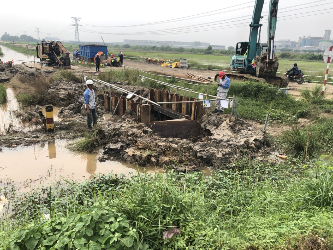
Survey of construction layout
The construction team, the survey team discussed and calculated the actual characteristics of the ground, the existing obstacles if any (lines, underground cables, sewer pipes, ...), determined the location of drilling machines, welding nests. Combination of CW DN2600 pipe and welding of reinforced steel pipe, preparation for pulling, construction plan, gathering equipment and materials, possible obstacles and proposing solutions to speed up progress (if necessary).
Thus, it can be seen that the difficulties mainly stem from natural conditions: ground, geographical location, weather. To overcome these difficulties and speed up the progress, the contractor determined to follow the following criteria:
Optimal resource mobilization for all stages.
Reasonable arrangement of resources to coordinate smoothly between construction sites, with local authorities, functional agencies and the Investor without creating downtime during the construction process.
Strictly control, find potential risks, focus on handling immediately to prevent these potentials from developing into problems.
9.2 MOBILE MACHINERY, EQUIPMENT AND HUMAN RESOURCES
Based on survey data, Minh Phuong has selected suitable equipment and materials to gather to the project. The correct and sufficient selection ensures efficient construction, on schedule and minimizes the costs incurred.
Construction personnel to carry out the project must ensure that they have been trained in safety and have specialized certificates appropriate to the field in charge.
9.3 ROAD SURFACE OF DRILLING AREA
When starting underground drilling through the road, the construction unit will install a speed limit sign of 5 km/h.
Reinforce the roadbed by spreading 10mm thick steel plates on the road surface at the underground drilling site.
Appoint people to be on duty 24/24 h at the construction site to remind vehicles to limit speed when passing through the construction area.
The borehole is filled with betonite, after pulling the pipe, it is filled with low grade concrete or soil cement concrete to compensate for the empty hole in the pipe drilling process.
After pulling the pipe, the borehole part is reinforced with low grade concrete or soil cement concrete, which is fixed and kept stable after 72 hours before removing the reinforced corrugated iron layer on the road surface.
9.4 PREPARATION OF DRILLING WORK
Using an electronic total station to determine the scope of the construction site in the field.
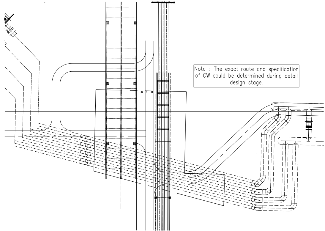
Build 04 2600mm diameter pipelines, can change the number of pipes with 2 pipes (DN3700) at the detailed engineer stage.
Barriers, construction site signs
10. SURFACE DRILLING STAINLESS STEEL PIPE REINFORCED DN2800
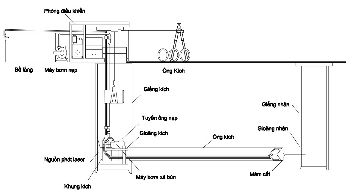
High power hydraulic jacks are used to push special pipe joints into the ground with front mounted locomotives.
The construction of the drainage system by underground jacking technology is carried out through the following steps:
1. Survey the condition and condition of the ground before construction and measure and determine the construction location.
2. Construction of jacking wells and receiving wells.
- Jacking well: In order to be able to execute underground jacking drills and install pipes with a depth of 9.0m compared to the road surface, the minimum depth of construction pits is 9.5m deep. Dimensions of the excavated hole are: length=3.0m; width = 3.0m; depth=9.5m. The jack drill is placed at a height of +0m above the bottom of the jacking well. The jacking well is reinforced with Larsen piles to prevent landslides during the construction process.
- Receiving well: dug to a depth of 9.5m above the road surface. This well has the effect of opening the borehole, receiving the pipe and constructing the pipe winch to help orient the pipe. The cross-section of the receiving pit has the following area: length=3.0m; width = 3m; depth=9.5m. The well received reinforcement of Larsen piles to prevent landslides for the receiving well during the construction process.
3. Precise positioning of soft eye position at jack-well outlet and receiving-well inlet.
- Soft eye positioning is based on the design elevation of the bottom of the culvert.
4. Transporting construction equipment and tributes to the construction site.
- The sluice gates have a different structure from the open excavation culverts to be suitable for pipe jacking. There are 3 types of tributes:
+ Standard pipe: This culvert has a normal structure, only the position of a crane hook is used to lower the drain into the size of the pipe.
+ Grouting pipe (Grouting pipe): This sluice has the same structure as a regular culvert but has 3 additional holes located 120o apart along the circumference of the culvert to serve the pumping of Bentonite grout around the culvert wall.
+ Intermediate pipe: This is a pair of drains including male pipe (Male pipe) and female pipe (Female pipe). The intermediate jack is arranged between these two drains. After jacking the entire sewer line, the intermediate jack is dismantled and pushed together.
5. Installation of ground support equipment for jacking: Crane truck, sludge settling tank, dredger, generator, Bentonite pumping station.
- Bentonite pumping station has the purpose of pumping Bentonite mortar to the outside around the pipe body to reduce the friction between the soil and the pipe wall.
6. Installation of supporting equipment in the well for jacking: Mud pump system, ventilation system, control system, hydraulic system, electrical system, bentonite pumping system, laser guidance system , gasket to prevent water, jet wall.
7. Install the main jacking system and connect with supporting devices: Hydraulic jack, push jack ring: contact washer between drain and main jack, drill head, intermediate jack (if any).
8. Operate the jacking system to bring the drill head into the ground to start the pipe jacking work. Install successive culverts behind the drill head and intermediate jacking stations (if necessary) until the culvert and drill head enter the receiving well.
- During the pipe jacking process, it is necessary to monitor the main jacking force. If the main jacking force is too large, it can burst the drain, then it is necessary to install intermediate jacking stations to reduce the main jacking force.
- The positions of intermediate jacking stations are determined based on calculations.
9. At the location of the receiving well, install the receiving gasket, the jack receiving frame.
10. Transport the drill head and jacking aids in the tunnel out of the receiving well. Clean the construction site according to regulations.
Drilling technology
Drilling fluid used for pipe pulling work
Drilling fluid is an important component of successful pipe pulling. Basically, drilling fluid is a mixture of water, bentonite and additives. The amount of bentonite used is calculated based on the engineering geological parameters and the diameter and length of the borehole.
Drilling fluid has the following functions:
Breaking, mixing soil, rock, sand in the tunnel where the drill head and break head pass when being pumped and compressed with high pressure.
Establish and maintain tunnel stability (avoid tunnel collapse).
Lubricate the drill head, break head and drill rod, reducing heat concentration on these tools.
Transporting soil, rock, sand in the tunnel to the outside.
Another important property of drilling fluid is that it can be reused through the use of recycling equipment.
Xem thêm BIỆN PHÁP THI CÔNG KHOAN NGẦM 04 TUYẾN ỐNG CW DN2600 >>
CÔNG TY CP TƯ VẤN ĐẦU TƯ & THIẾT KẾ XÂY DỰNG MINH PHƯƠNG
Địa chỉ: Số 28B Mai Thị Lựu, Phường Đa Kao, Q.1, TPHCM
Hotline: 0903649782 - (028) 3514 6426
Email: nguyenthanhmp156@gmail.com
Xem thêm